How to use the GPIO Connectors on a breadboard and make LED lights blink.
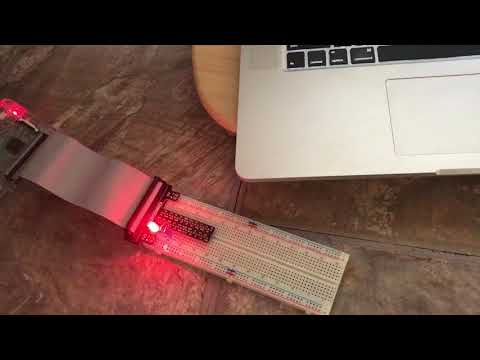
 The resistors and LEDs are added to GPIO pins 17 and 22 which map to Inputs 11 and 15 respectively. Note that the long end of the LED connectors which are positive are added to the GPIO pins while the short end of the pins are added to GROUNDED connectors.


Click on the video link below to see the end result 😀.