Build Guide (Wired)
The wired build makes use of an Pro Micro microcontroller board and the QMK Firmware
| Part Name | Amount | Notes / Link |
|---|---|---|
| PCB | 2 | See the release page for the latest Gerber files or use KiCad to generate them |
| Serial/OLED Shield | 2 | You will need two serial/oled shields in addition to the main PCB. See the release page for the latest Gerber files or use KiCad to generate them (I ordered them with a thickness of only 0.6mm to keep a low profile) |
| Case | 2 | You may go without a case but to protect the TrackPoint module, I suggest to either use a 3d printed case or to use a top/bottom plate. For the OLED display you may also want to get some acrylic glass (3mm thick). |
| Pro Micro (USB-C Version) | 2 | or a compatible microcontroller board. I design the case with the measurements of a Pro Micro USB-C. |
| Microcontroller Sockets | 4 | (Optional) Note: I did not use sockets and soldered the pro micros directly with the pin headers to the PCB. If you are going to use sockets and the 3dp case, you may need to modify the case parameters to match the measurements. |
| Diodes | 36/42 | 1N5819 SOD323 |
| Switches | 36/42 | Only Kailh Choc switches are supported (PG1350) |
| Hot Swap Sockets | 34/40 |
(Optional) Note that two switches have to be soldered due to space restrictions of the TrackPoint mo. |
| TRRS connectors | 2 | The same type which is used in other split keyboards like the Corne or Kyria. Technically even TRS should work as only serial communication is supported between the halves |
| Tactile push button | 2 |
(Optional) e.g. https://www.sparkfun.com/products/8720 |
| TRRS Cable | 1 | A TRS cable does also work |
| M2 Case Spacers | 4 | The height depends on whether you are going to use hot swap sockets and/or a TrackPoint module. I am using 4mm spacers together with hot swap sockets and a TrackPoint |
| M2 Inserts | 2 | |
| M2 Screws | 10 + 2 | For the M2 spacers, length around 4mm, +2 if you going to use a TrackPoint |
| 4.7kΩ Resistor (OLED) | 2 | Only required if you a want to use an OLED display that does not come with pull down resistors |
| OLED Display | 2 | (Optional) |
| 4.7kΩ Resistor (TrackPoint) | 2 | Only required if you are going to use a TrackPoint, SMD 0603 Footprint |
| TrackPoint Stem Extension | 1 | A stem extension for the TrackPoint is required. The hole in the top plate between the two inner columns is only 2.6mm in diameter I am using a labret piercing as stem extension. It is glued onto the TrackPoint module and is 6mm long and has a diameter of only 0.8mm
|
| 100kΩ Resistor (TrackPoint) | 1 | Only required if you are going to use a TrackPoint, SMD 0603 Footprint |
| 2.2uF Capacitor (TrackPoint) | 1 | Only required if you are going to use a TrackPoint, SMD 0603 Footprint |
| TrackPoint | 1 |
(Optional) Only supported on the master side (by default right halve) The PCB is designed for a TrackPoint of a Thinkpad X230S, X240, X240S, X250, X250S, X260 or X270 |
- Solder the diodes to the bottom of the PCB
- If you are going to use a TrackPoint you have also to solder the resistors R3, R4 and R5 and the capacitor C1 to the bottom of the PCB (only on the halve where you will connect the TrackPoint)
- If you are going to use an OLED display, you may want to solder also the resistors R1 and R2 to the bottom side of the PCB
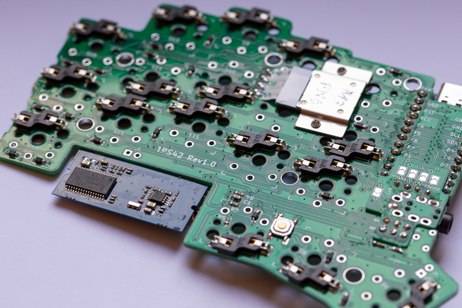
- Solder the hot swap sockets to the PCB
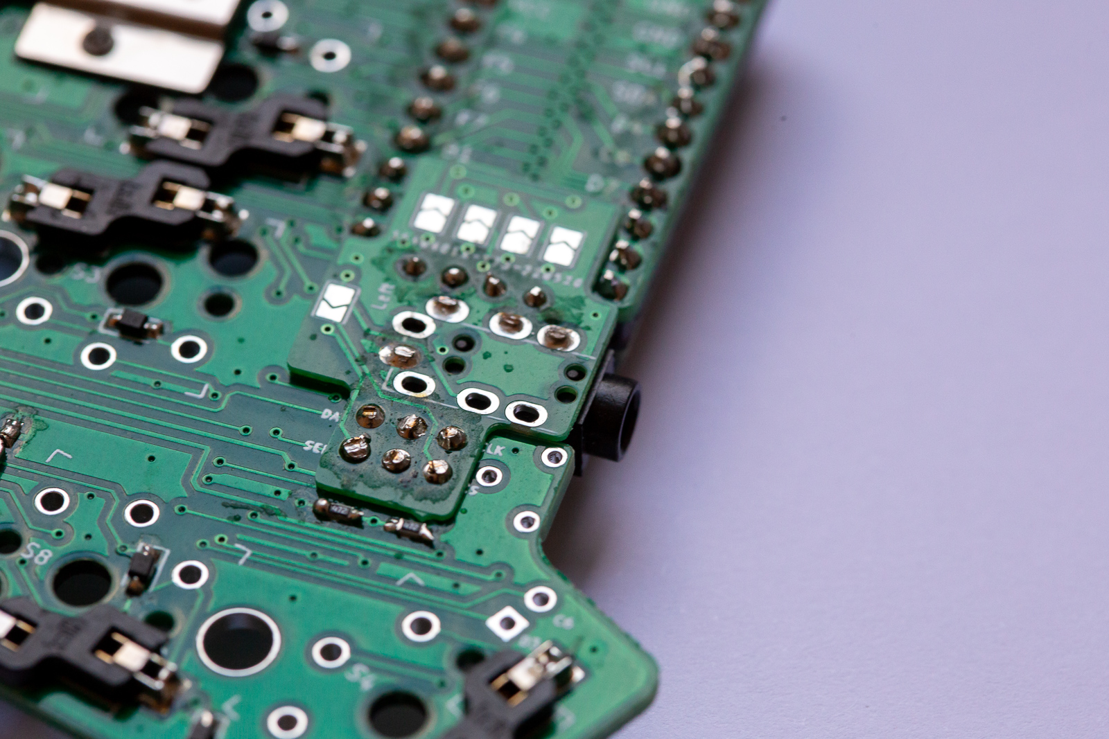
- Prepare two Serial/OLED shields (one for each side). Solder the TRRS connector and bridge the jumpers of the corresponding side (left/right) NOTE: Before 2022-12-13, the wrong (older) gerbe-zip file was uploaded in the release section. This is now corrected. If you've used the older version, you have also to bridge the single right jumper at the bottom of the left half: https://imgur.com/a/9kLwgpa
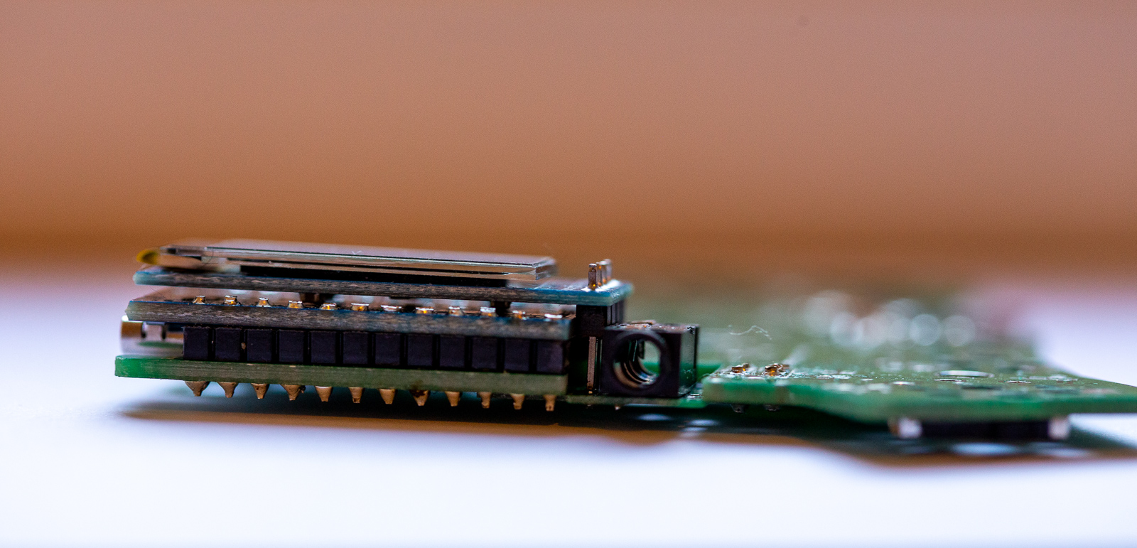
- Solder the Serial/OLED shield from the bottom to the main PCB. Make sure it is as flush as possible
- Solder the Pro Micro (facing down) to the top of the PCB. Make sure to bridge the jumpers on the bottom side of the PCB
- Solder the optional OLED display
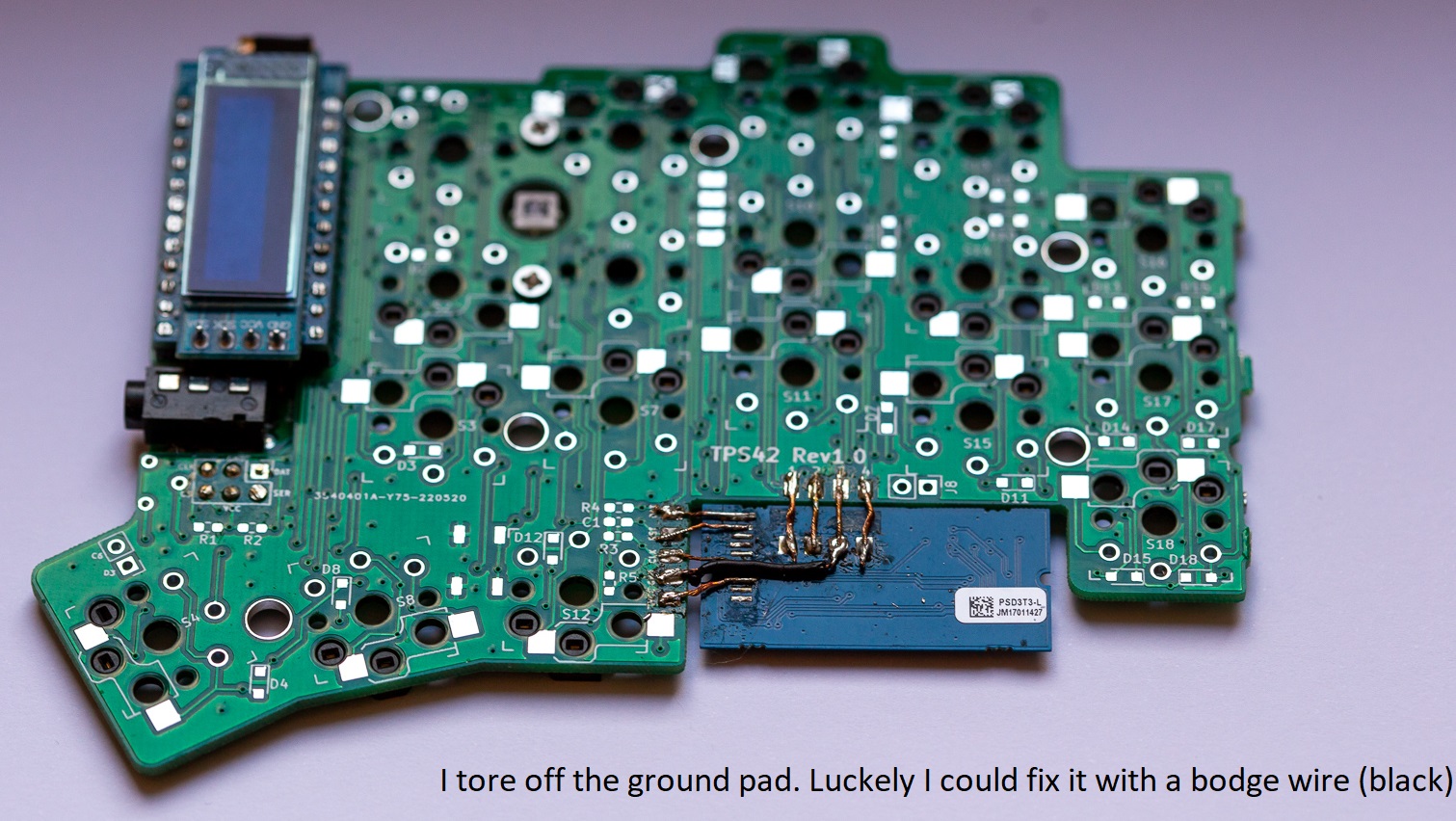
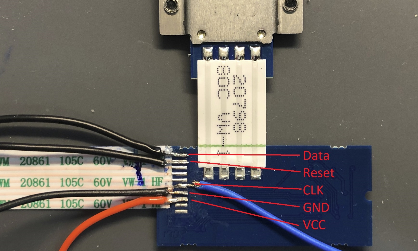
- Solder the optional TrackPoint circuit PCB to the contacts of the main PCB. I used thin wires so they don't get into the the way when using the 3dp case
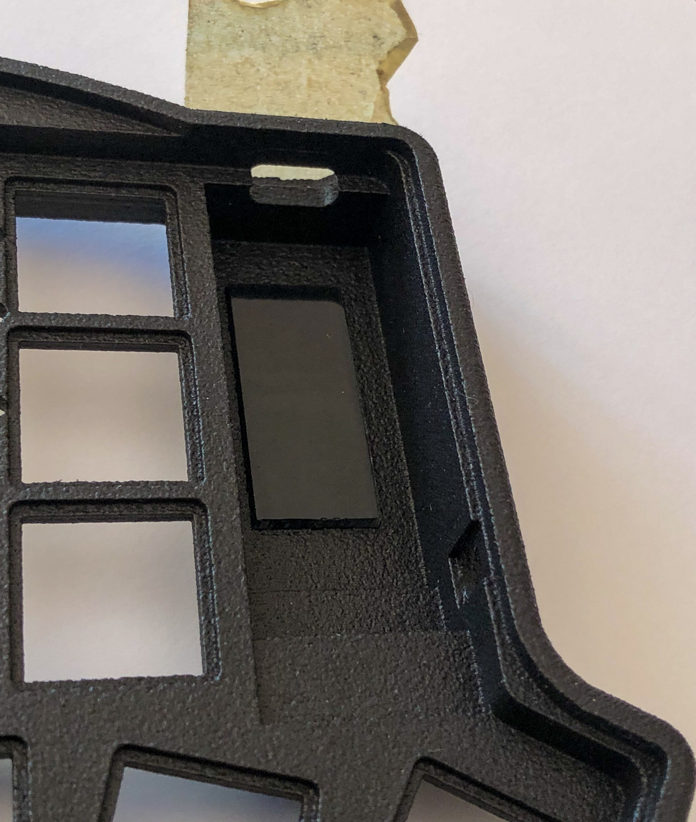
- Glue the acrylic glass window into the cutout of the case. I used 3mm thick acrylic glass (cutout has a 2mm border) and filled the remaining 1mm with hot glue
- Install the M2 spacers (two per side) with two screews to the case and the M2 insert.
- Now you can put the PCB into the case
- Before adding the TrackPoint module, insert and solder the two switches S1 and S6 (the ones without hot swap sockets)
- Glue the labret piercing to the TrackPoint module and install it with two M2 screws to the case/PCB. You may want to use some tape to make sure there are no shorts between the TrackPoint module and PCB
- Install the remaining switches.
- Close the case by screwing the bottom plate into place and add your keycaps
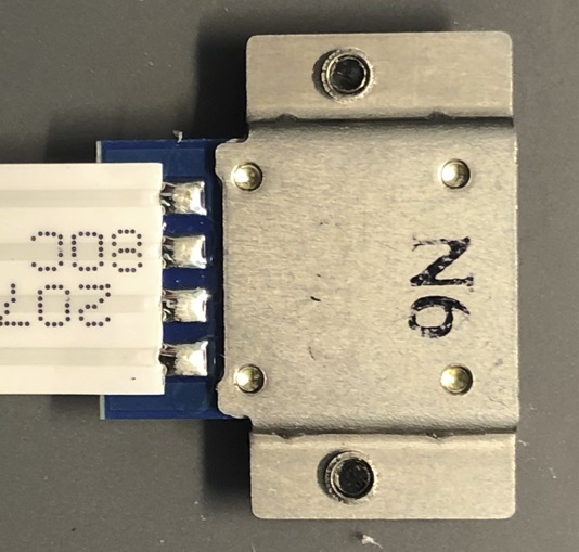
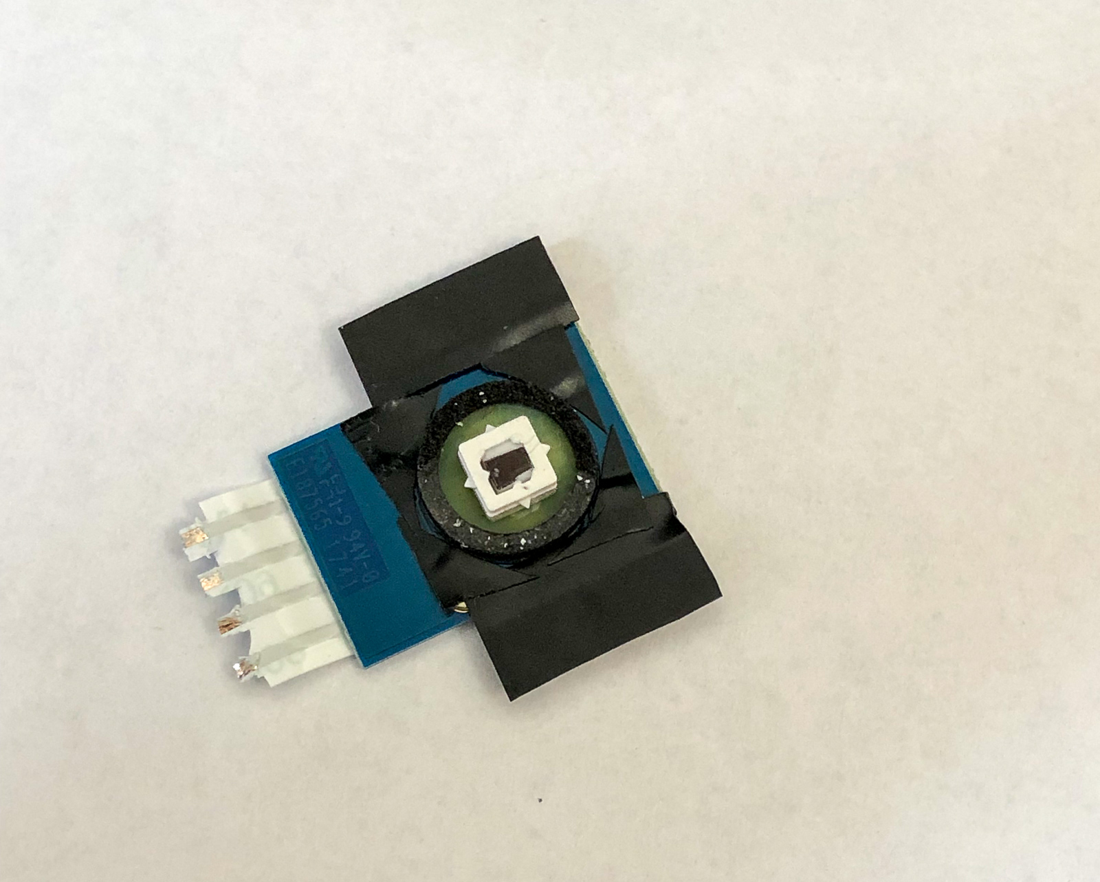
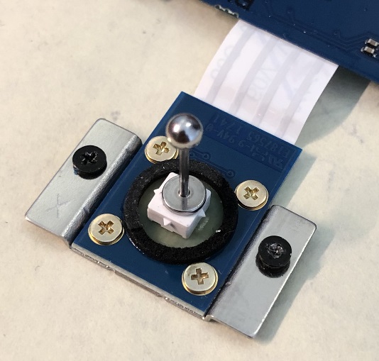
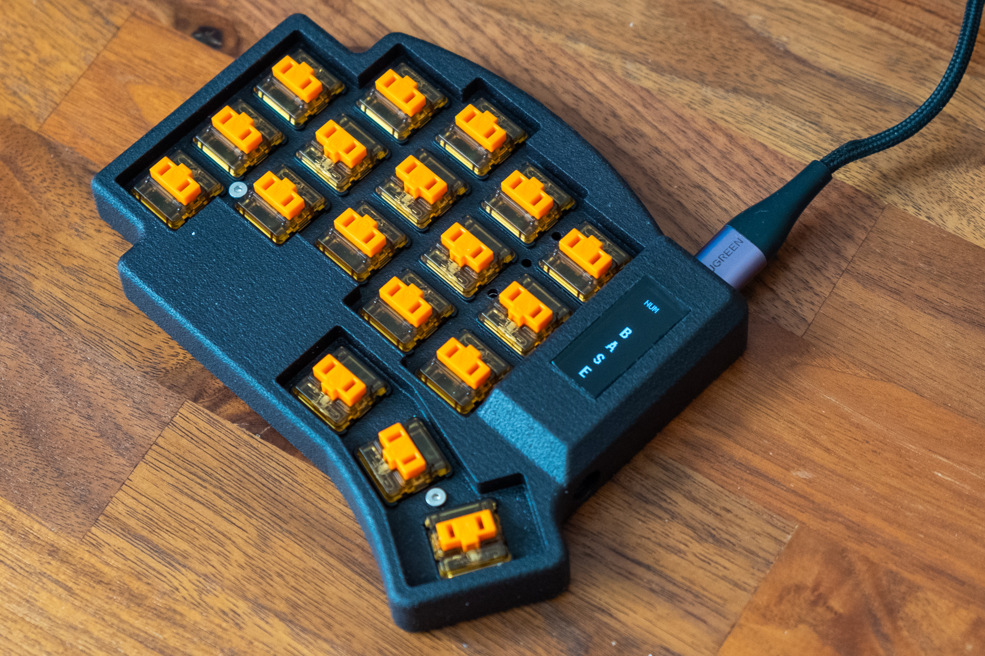
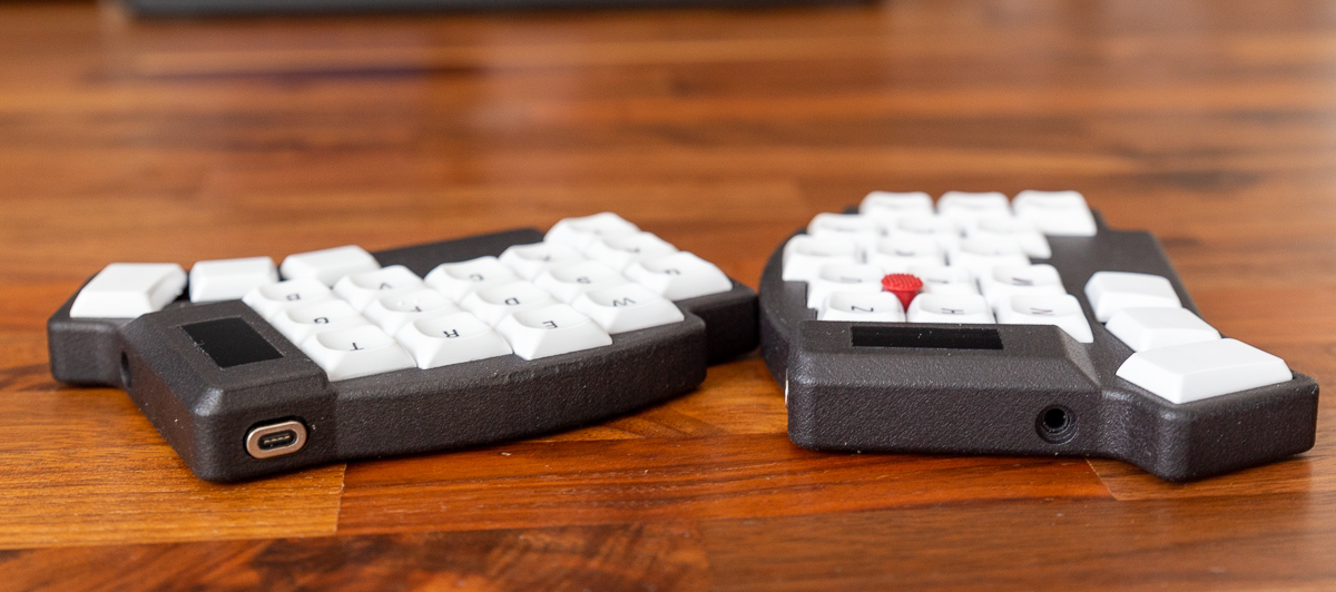
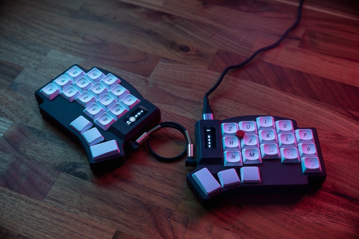
Some Pictures for visual aid:
 |
 |
 |
 |
|---|---|---|---|
 |
 |
 |
 |
 |
 |
 |
 |
I haven't created a pull request to add the configuration to the QMK repository yet. But you can find it here in my fork: https://github.com/crehmann/qmk_firmware/tree/keyboard/add_tps42/keyboards/tps42