Gate circuits_eac3
Each circuit is internally represented as an array of unsigned longs (defined by constant GENOME_ITEM_TYPE). These unsigned longs are virtually composed in layers of two types:
- connector layers (defining connections between nodes) and
- function layers (defining function nodes).
Connector and function layers are alternating, starting with connector layer.
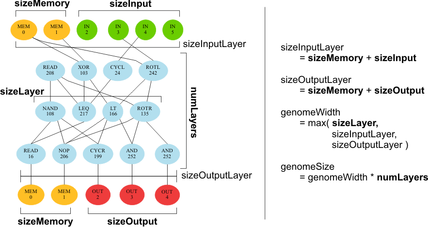
Circuit dimensions are calculated based on settings in [configuration file](State-file-(XML)_eac3). Each layer is internally as long as the longest one (information accessible from genomeWidth variable in global resources). For exact dimensions see the diagram below; parameters displaid in bold are directly set via the configuration, other are calculated automatically.
Note: Memory is considered only if enabled (via useMemory).
Connectors define relative offsets of nodes connected to corresponding node. Each internal node has at most numConnectors connections (value from global settings). The leftmost connectible node has connector value of 2^0=1, the rightmost has connector value of 2^( numConnectors - 1).
Connector number is computed as sum of all present connectors. If numConnectors is even, connectors are shifted half-a-slot to the left (see example). Edge connectors are wrapper to the other side.
example: numConnectors = 4
1_0   1_1   1_2   1_3   1_4   1_5
       \-----\-----|-----/            (no other connectors applicable)
                   |
2_0   2_1   2_2   2_3   2_4   2_5
Connectors in the first and last layers are relative as well, but the restriction of numConnectors does not apply. Restriction of sizeInputLayer and sizeOutputLayer are taken instead.
BEWARE!
Connectors in text outputs are absolute for easier input/output. See output files description for more information.
Relative and absolute connector masks can be easily converted to one another using the functions provided in CircuitCommonFunctions file (see in-code documentation for more info).
The rightmost byte of unsigned long denotes function used (according to constants in EACConstants.h). The remaining 3 bytes are inside-node arguments used if the node needs them (the left-most byte is argument 1, followed by arguments 2 and 3).
The following set of functions is used in circuits. Only a subset may be allowed for particular run, settings are located in [configuration file](State-file-(XML)_eac3). External routines can be used via the EXT functions.
-
NOP
- passes input from first connection uncganged, other connections are ignored
- default value (if no connections) is 0
-
CONS
- passes inside-node argument to output
- all input connections are ignored
-
AND, NAND
- all input connections are processed
- default value is 255
-
OR, XOR, NOR
- all input connections are processed
- default value is 0
-
NOT, SHIR, SHIL, ROTR, ROTL
- only the first input is processed, others are ignored
- bit-shifts and bit-rotations rotate by inside-node argument
- default value is 0
-
EQ, LT, GT, LEQ, GEQ
- compare first input to the second input
- other inputs are ignored
- false output (default) is 0, true output is 255
-
BSLC
- bitselector based on the mask saved in inside-node argument
- processes first connection input only, others are ignored
- default value is 0
-
READ
- return byte from input layer with index [inside-node argument % sizeInputLayer]
- all input connections ae ignored
-
EXT
- calls external function based on inside-node argument
- inputs used and default value are based on external functions
![]()
--
You are on EACirc 3 wiki!
--
Building notes
Running notes
Recommencing computation
--
Framework components
Circuit back-ends
Main computation loop
Projects
Evaluators
CUDA support
Testing
Known bugs
Third party libraries
I/O-Files structure
Java bytecode simulator
--
Project eStream
Project SHA-3
Project CAESAR
Project Files
--