Booth's multiplication algorithm is a multiplication algorithm that multiplies two signed binary numbers in two's complement notation. The algorithm was invented by Andrew Donald Booth in 1950. In this project, we have designed and implemented the Booths Algorithm for Multiplication using the data path and the control path. The module designed is capable of performing multiplication of two 5-bit signed numbers which generates a 10-bit result.
- Booth's Algorithm
- Tools Used
- Flow Chart
- Data Path
- Control Path and State Diagram
- Block Diagram
- Simulation Results
- Implementation
- Conclusion
- References
Booth's multiplication algorithm is a multiplication algorithm that multiplies two signed binary numbers in two's complement notation. In the conventional shift and add operation, for n-bit multiplication, we either add 0 or the multiplicand to the 2n-bit partial product, shift the partial product to the right, and repeat this entire process n times. However, while applying Booth's algorithm, we can avoid the additions whenever consecutive 0's or 1's are detected in the multiplier. Hence, this is a huge improvement from the conventional multiplication algorithm, and it makes the process a lot faster.
- In Booth's algorithm, we inspect two bits of the multiplier (Qi and Qi-1) at a time
- If the bits are same (00 or 11), we only shift the partial product.
- If the bits are 01, we do an addition and then shift.
- If the bits are 10, we do a subtraction and then shift.
- Initially, Qi-1 is assumed to be zero.
Let us consider an example where we multiply two binary numbers using Booth's algorithm. We will multiply 7 and 8, and we will get 56 as the answer. Let M be the multiplier register, and Q be the multiplicand register. Also, let A be the temporary register used to calculate the product. Thus, in binary, we can write,
M = 00111, Q = 01000
As initial value of A is 0,
A = 00000
And finally, initial value of Q(-1) will be 0
Q(-1) = 0
Now, the Booth's algorithm will multiply the two numbers as follows:
A = 00000, Q = 01000, Q(-1) = 0
As number of bits is 5, the multiplication will be carried out in 5 steps.
As Q(0) = 0, Q(-1) = 0, the bits will be shifted as follows:
A(MSB) -> A(MSB-1:0) -> Q -> Q(-1)
A = 00000, Q: 00100, Q(-1) = 0
As Q(0) = 0, Q(-1) = 0, the bits will be shifted again:
A = 00000, Q = 00010, Q(-1) = 0
As Q(0) = 0, Q(-1) = 0, the bits will be shifted again:
A = 00000, Q = 00001, Q(-1) = 0
As Q(0) = 1, Q(-1) = 0, M(00111) will be subtracted from A(00000), and the result will be stored in A:
A = 11001, Q = 00001, Q(-1) = 1
After this, the bits will be shifted again:
A = 11100, Q = 10000, Q(-1) = 1
As Q(0) = 0, Q(-1) = 1, M(00111) will be added to A(11100), and the result will be stored in A:
A = 00011, Q = 10000, Q(-1) = 0
After this, the bits will be shifted again:
A = 00001, Q = 11000, Q(-1) = 0
Hence, the final result is {A,Q} = (0000111000)2 = (56)10
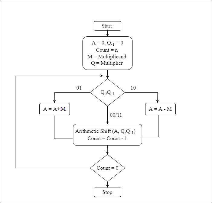
Fig. 1 : Flow Chart
Following are the steps followed in the flow chart:
- Step 1: Start
- Step 2:
- Initialize register A and flip-flop Q(-1) to zero by clearing its contents.
- Initialize the counter with 'n'(number of bits).
- Initialize register M with the multiplicand.
- Initialize register Q with the multiplier.
- Step 3: Check {Q(0),Q(-1)}
- If {Q(0),Q(-1)} = "00" or "11, then go directly to step 4.
- If {Q(0),Q(-1)} = "01", then add M to A, store in A, and go to step 4.
- If {Q(0),Q(-1)} = "10", then subtract M from A, store in A, and go to step 4.
- Step 4:
- Do an arithmetic shift operation on {A,Q,Q(-1)}.
- Decrement counter.
- Step 5: Check counter
- If counter!=0, go to step 3.
- If counter=0, go to step 6.
- Step 6: Stop

Fig. 2 : Data Path
The above fig shown depicts the data path of the booth's multiplier.
- It contains 3 Shift registers to store Multiplicand (M), Multiplier (Q) and the partial product (A). There is a common data_in line to load the values to M and Q. The values are loaded using control signals ldM and ldQ respectively. Along with ldQ, shift register Q is provided with few more control signals such as clrQ and shiftQ which are used to clear the register and shift the contents of register respectivly. The shift register A is initialized with 0. The shift register A is also provided with same control signals as that if register Q that are ldA to load value to A, clrA to clear the register and shiftA to shift the content.
- There is one D type flip flop present which stores the value of LSB of Q register. The input to the flipflop is Q[0] and the output is qm1. But while computing the output of flipflop is assumed as Q[-1]. There is a control signla present to clear the flip flop.
- As we saw previosly, the booth's algorithm checks the bits Q[0]Q[-1] and decides whether to add partial product to multiplicand and then shift (case : 01) or to sub multiplicand from partial product and then shift (case : 10) or only shift the contents (case : 00/11). In first two cases i.e. when Q[0]Q[-1] are either 01 or 10, addition or subtraction operation needs to be performed. Thus an ALU i.e. an Arithmetic Logic Unit is present which carries out the addition and subtraction operation depending upon the select input applied. The select input is the control signal to the ALU which comes from the control path and is based on the value of Q[0]Q[-1]. The result of ALU is loaded back to A. The number of shifting operations is same as that of the number of bits which are loaded in the shift registers (both registers should be loaded with equal number of bits.) Here we have loaded 4-bit signed numbers thus the shifting operation needs to be performed 5 times. There is a down counter present to serve this purpose. It has control signal 'ldcount' which loads value 101 to counter and another control signal named 'decr' to decrement it to zero.
- While reading the output of booth's multiplier we read from the MSB of register of partial procut i.e. A to LSB of Multiplier i.e. Q[0] and leave Q[-1].
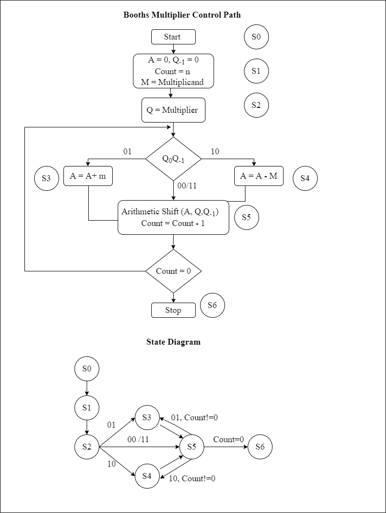
Fig. 3 : Control Path
The above fig depicts the control path of the Booths multiplier.    The control path is a controller which provides different control signals to the different data path modules. There are some feedback signals which originate from data path and are fed to control path. These signals are necessary for state trasition. The control path module is a Finite State Machine. There are some finite states and depending in which state currently the module is, the control signals are activated. The above diagram shows the states assigned to the block.
- S0 : The module starts
- S1 : When module is in state S1, the partial product shift register A gets loaded with all zeros. The count gets loaded to the counter and the Multiplicand M gets loaded through the data_in.
- S2 : In state S2, the Multiplier value gets loaded.
- S3 : If the Q(0)Q(-1) bits are 01 then module goes into state S3 where the value of multiplicand M and partial product A are loaded into ALU and are added with each other(A = A+M). The result again is stored into the register A.
- S4 : If the Q(0)Q(-1) bits are 10 then module goes into state S4 where the value of multiplicand M and partial product A are loaded into ALU and are subtracted (A = A-M). The result again is stored into the register A.
- S5 : The module changes its state from S2->S5 or from S3->S5 or from S4->S5 depending upon the the values of Q(0)Q(-1). The bits of A and Q gets shifted in this state except the MSB of A.
- S6 : Module stops if counter reaches to zero. Depending upon the state and the feedback from data path, different control signals are set or reset.

Fig. 4 : Block Diagram
The above figure depicts the block diagram of the booth's multiplier. This shows the flow of signals in between control path and data path. Control path provides input to the data path. Following are the signals in the block diagram:Control path to data path:
- ldA : To load the partial product register.
- clrA : To clear the partial product register.
- shiftA : To shift the data in partial product register.
- ldQ : To load the multiplier into the register.
- shiftQ : To shift the data in shift register Q.
- ldM : To load the multiplicand.
- clrff : To clear the flip flop.
- addsub : This acts as the select line of the ALU.
- ldCount : To load the count value into the counter.
- decr : To decrement the counter.
Data path to control path:
- iszero : To check whether counter has reached to zero or not.
- q0, qm1 : Q(0) and Q(-1) are the bits which decide the ALU operations.
Signals exclusive to control path:
- start : This bit is set to start the multiplication.
- done : This bit is set when the multiplication is finished.
Here the results are shown for the following test case. M = 0111 (7) Q = 1000 (8) The expected answer is 111000 i.e. 56

Fig. 5 : Command Line Output

Fig. 6 : GTKWave Graphical Output
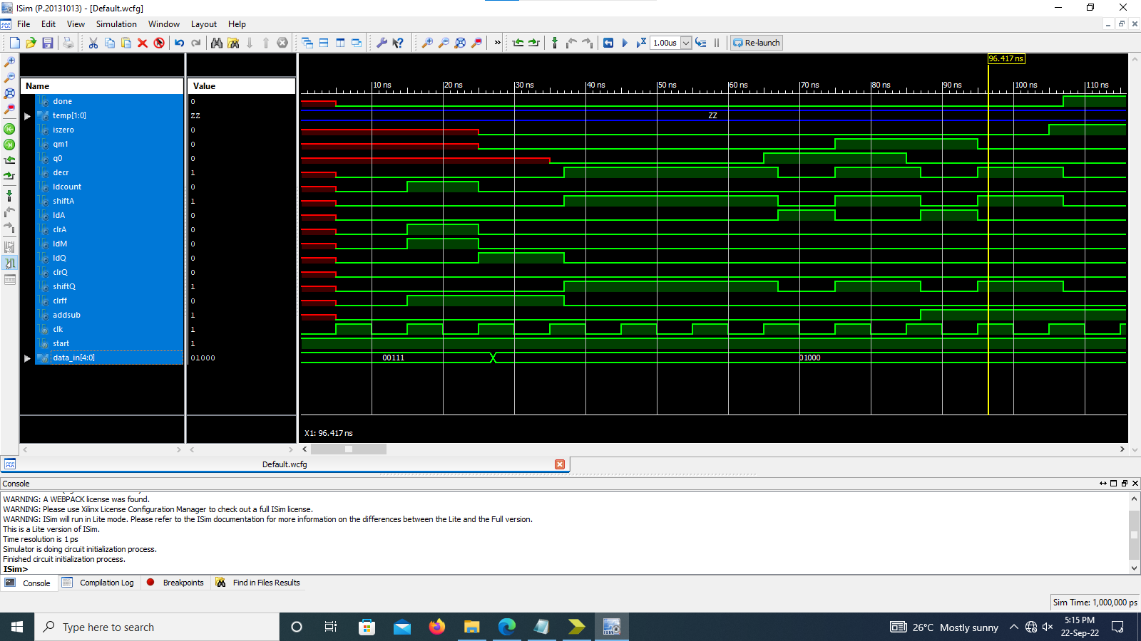
Fig. 7 : Xilinx Graphical Output
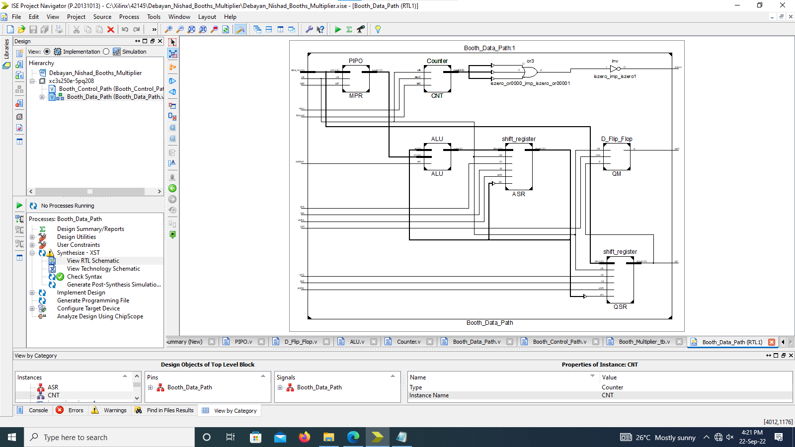
Fig. 8 : Xilinx RTL Schematic
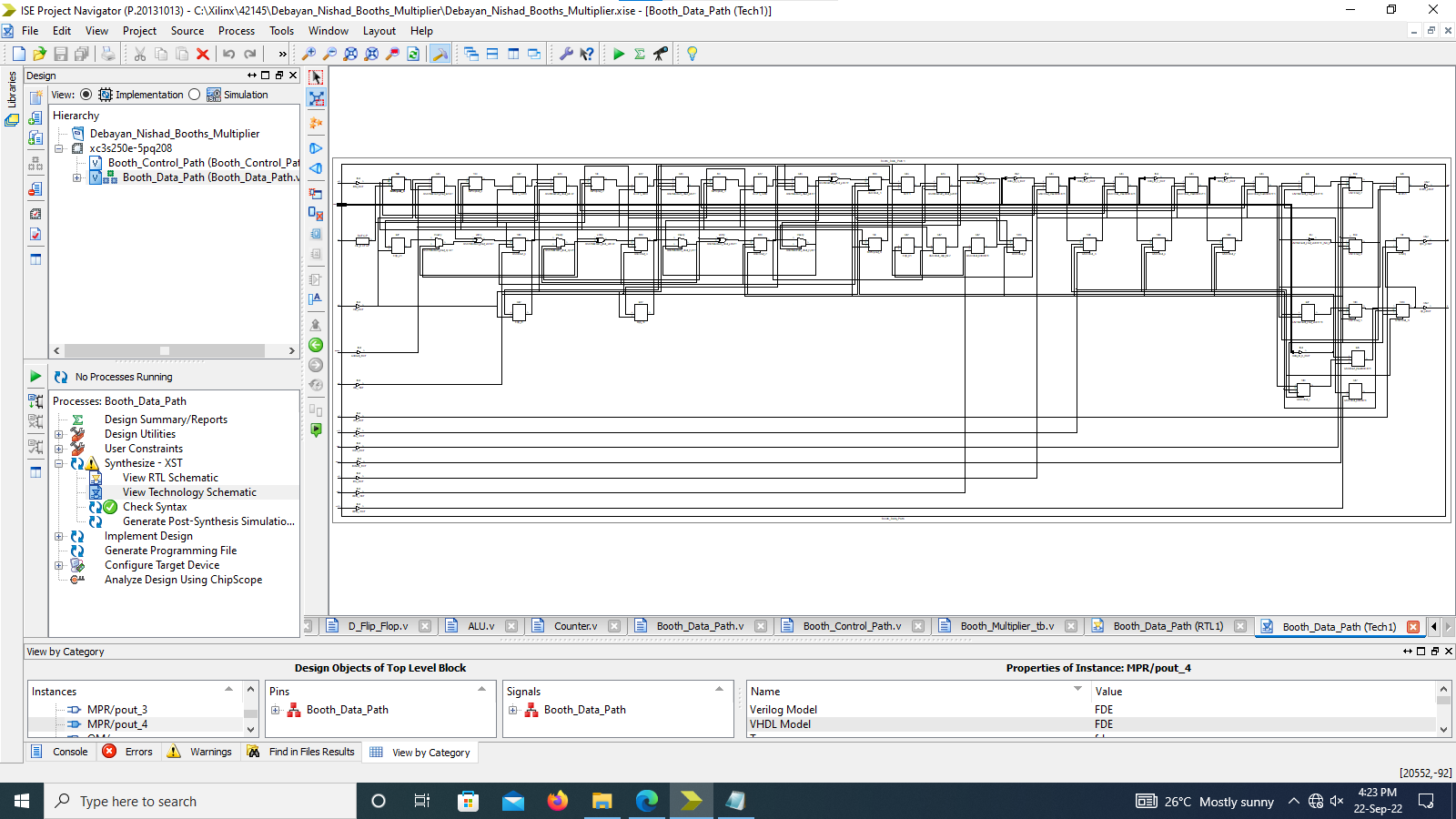
Fig. 9 : Xilinx Technology Schematic
In this project, we have successfully designed the Booth's Multiplier using Data path and control path design. It is found that the multiplication done using booth's algorithm is much faster than the conventional add and shift algorithm. The design is simulated using two different softwares i.e. Icarus Verilog and Xilinx ISE iSim. After successfull simulation, the design is synthesized on FPGA and results are verified.