
This repo is a Proxxon MF70 mill CNC conversion based on 3D printed and off-the-shelf mechanical parts, with Y axis extended from 46mm to 90mm and Z axis extended by 15mm.
I also included a couple parts for if you just want to extend the Y axis for hand milling only, but CNC is the main point of this repo.
I'm lazy to create a name for it, but in the spirit of the Bubblegum conversion I printed all the parts in yellow so I'm just calling it that.
If you are here you probably already have one, but the Proxxon MF70 is a cheap, tiny 3-axis mill that sells for around USD 400, sometimes as cheap as 200-300 on Craigslist or eBay and is been a popular target of CNC conversions by hobbyists living in small spaces. The full machine with CNC conversion and enclosure is no larger than a typical 3D printer.
This mill has a number of limitations, but perhaps the biggest of which is that the Y axis is only limited to 46mm of travel. It is fairly straightforward to extend this Y axis to 90mm. The Z axis is also limiting as it only has 70mm of travel, starts from uselessly low, which makes it hard to use a 4th ("A" or rotational) axis. Both of these limitations are addressed in this conversion.
There are other limitations with this cheap mill but not addressed here. (Anti-backlash nuts, brushless motor upgrade, new spindle, ACME screws, ball screws, etc. -- but you can still do these things on top of this conversion if you wish.)
If you have a 3D printer to print the parts in this repo, and want a mini CNC mill for $500-$600 total, this is it. If you want to spend $1200 or more, there are better options available.
I wasn't fully happy with any of the existing conversions.
The AliExpress conversion kits are cheap but don't address Y axis or Z axis limitations, use self-tapping screws to hold the entire weight of stepper motors which I am not confident about, and use only 2 out of the 4 mounting screws to hold NEMA23 motors, which is not good for stability. I do, however, like their couplers that attach to the existing handles of the MF70 and use those couplers in this conversion.
The Robotpark conversion has the same issues as the AliExpress kit at a 5X-10X markup, and judging from pictures, seems to just use the same parts as the AliExpress kits.
Proxxon's own CNC-ready MF70 allows a greater Y axis travel of 70mm, which is better than the 46mm, but I am achieving 90mm here. It also does not address the Z axis height at all.
The Bubblegum conversion is a nicely designed kit but addresses neither Y nor Z axis limitations. I take a couple inspirations from it.
This conversion involves taking off the knobs fully and purchasing additional shaft couplers, which I also didn't want to do, though if you'd like to do that, you can still use the mounting parts in this repo, and might just need to adjust the M5 spacer lengths.
This conversion is a lot of work and addresses backlash but does not solve the Y or Z axis limitations.
There are a number of other complicated DIY conversions out there that do address the Y and Z axis limitations, but I wasn't happy with any of their designs or complexity. Some involve 5 billion parts, some involve machining metal parts (which is great after you have a CNC mill but not before), some people have effectively replaced the entire machine, which is impressive and I have a lot of respect for, but it is too much for me (If I wanted to do that I might as well build the machine from scratch).
I wanted this to extend the Y and Z axis and stick to 3D printed parts and off-the-shelf parts while keeping the cost of conversion well under the cost of the mill itself.
- 3D printer and PETG, ABS, nylon, or other strong and chemically-resistant filament (do not use PLA!)
- Drill press
- Normal 3mm drill bit
- Extra long (120mm long) 3mm drill bit
- 90-degree countersink bit
- Dremel with cutting disc, or other tool that can cut threaded rods
- Blue Loctite
I include McMaster links for all the parts below for convenience, if you want to order them all in one go, and to serve as permalinks for what the exact part should look like. However, McMaster is expensive. If you want to save money you can find equivalent parts for almost everything on Amazon or eBay, though since the suppliers are constantly changing, there is no way to permalink to those sites. I have included Amazon search result links below, so verify that they match the specified dimensions before purchasing.
- 4 x M3 threaded rod, 2 cut to ? for X axis and 2 cut to ? for Y axis McMaster | Amazon
- 6 x M3 square nut, 5.5mm x 5.5mm x 1.8mm McMaster | Amazon
- 6 x ID=6 OD=12 L=4.5 thrust ball bearings McMaster | Amazon
- 1 x ID=6 OD=13 L=5 steel spacer McMaster
- 1 x ID=6 OD=13 L=2 steel spacer McMaster
- 8 x ID=5 OD=10 L=35 aluminum spacer McMaster
- 4 x ID=5 OD=10 L=45 aluminum spacer McMaster
- 4 x M5 L=50 flat head countersunk screws McMaster
- 4 x M5 L=65 flat head countersunk screws McMaster
- 4 x M5 L=75 flat head countersunk screws McMaster -- if you want to save money you can also just get a box of L=75 and skip the L=50 and L=65 above, but you'll have a hell of a time tightening lock nuts over the extra length
- 4 x M3 L=50 hex bolt socket cap screws
- AliExpress MF70 NEMA23 conversion shaft couplers -- you only need the "round parts" from the conversion kit -- there are some sellers which will sell only those parts to you AliExpress
- 3 x good quality NEMA23 motors with 5mm mounting holes (some have 4mm holes, but this kit is designed for 5mm) OpenBuilds | StepperOnline
For the CNC conversion, print all the parts starting with all- and cnc- in the stl/ directory.
If you just want a hand mill with Y axis extension, print everything starting with all- and hand- and ignore the CNC parts. You also only need a fraction of the off-the-shelf parts above, I'm sure you can figure it out.
I recommend printing everything at 100% infill with PETG, ABS, nylon, or other good material. I highly recommend you do not use PLA. Don't skimp on the infill, this is a mill, and if you're using PETG it will cost you a whopping $9 to print all these parts at 100%.
I recommend printing parts with large surface area (all-y-channel, cnc-x-rightplate, cnc-y-frontplate, cnc-z-topplate) with a brim to avoid lifting and warping at the corners, as the flatness of the bottom surface is crucial on many parts. If you don't have lifting/warping problems you can ignore this. Besides using a brim, for PETG, 2 things help to avoid warping: (a) use a higher bed temp like 90 C (b) use an enclosure or put your 3D printer in a closet so the ambient temperature rises to around 30 C - 40 C.
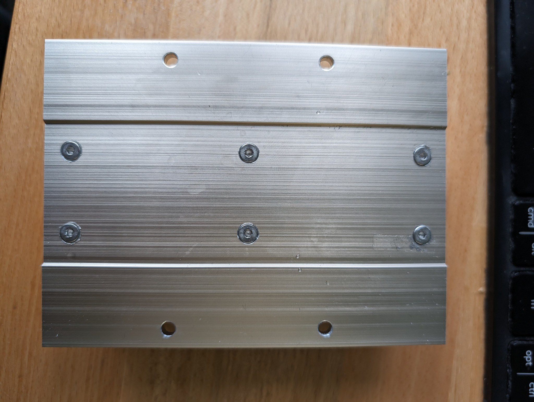
Remove the 2 axis stage, take apart the Y axis (noting that the lead screw is left-threaded), and then take apart the X axis (right-threaded) until you are down to this. Note that the "Proxxon" logo is on the front side, but we will take that off later, so you may want to mark the front side of the aluminum plate with a grease pen or scribe. Note that Proxxon's X and Y axis aluminum plates are intentionally NOT perfectly symmetrical by design, so when you put them back together the direction matters or you will not be able to assemble it.
Drop in the 3D printed "all-y-channel". It should fit snugly. Note that the channel is not symmetrical and there is a correct front and back side. You may want to mark the front end of this as well for convenience. You may have to slightly loosen the screws slightly to drop the channel in. Don't take them off fully yet, to ensure the holes you drill in the next step are properly aligned.

With a drill press and regular 3mm drill bit, drill out the 6 marked holes in the 3D printed channel all the way down and drill fully through the aluminum plate below. You can also, if you prefer, just barely touch the aluminum to mark the center, remove the channel, and then drill out the aluminum, to avoid aluminum chips accumulating inside the square nut inserts.


Remove the manufacturer-supplied end pieces of the Y axis. These will not be needed anymore. Countersink the holes from the back of the aluminum plate with a 90 degree countersink bit and verify countersunk screws sit flush.
Remove "all-y-channel", make sure the 6 slots on the side are clear of chips, and insert the 6 square threaded M3 nuts from the side.

Slide into the aluminum plate together with the carriage, brass spacer that goes with the carriage, and delrin nut, and use countersunk M3 screws to fix the 3D printed channel in place. With the Delrin nut in place, the carriage should be constrained by the ends of the 3D printed channel, and should slide smoothly from end to end. Make sure it does not have any resistance at the metal-plastic boundaries. If it does, your 3D printer may not be dimensionally accurate and you may have to do some sanding.
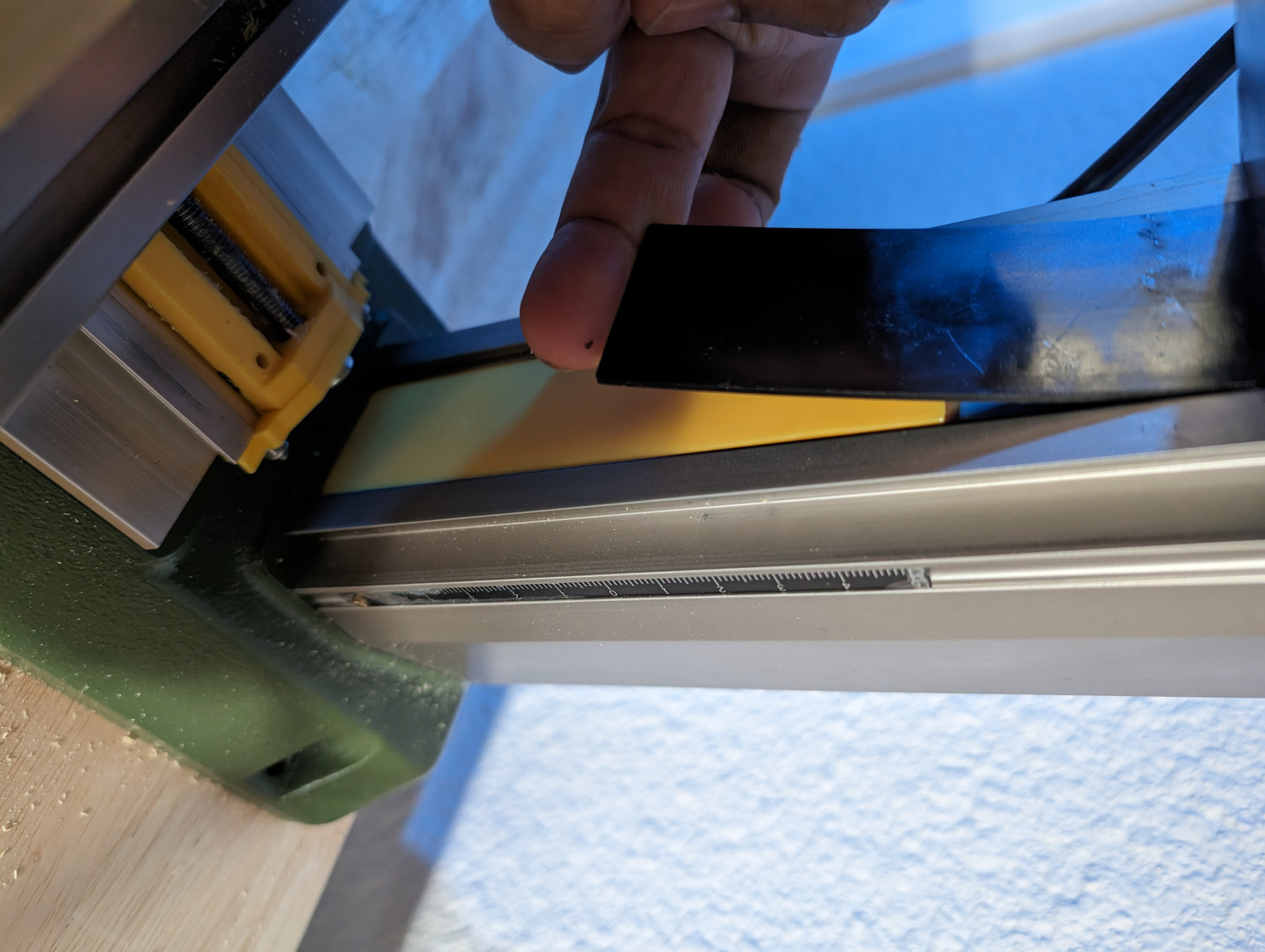
Use the 120mm extra-long M3 drill bit to carefully drill out the 2.5mm channels to 3mm. Use plenty of machining oil and go slowly to avoid breaking the bit. (We will no longer use the self-tapping screws and instead put M3 threaded rods though these channels which will hold things much more securely.) Work the drill from both sides to get all the way through the channel. Unfortunately I did not take a picture of this step for the Y axis, so here is a picture of the same procedure on the X axis for reference, but do this for the Y axis:

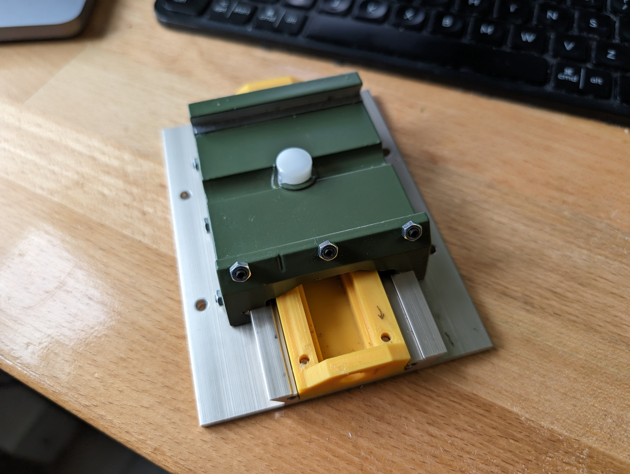
Install all-y-backplate on the back side. Install cnc-y-frontplate on the front side. Cut two M3 threaded rods to appropriate length with a Dremel. Use them along with washers and M3 locknuts on both sides to tighten them all in place. Make sure the rods do not protrude beyond the locknut on the front side.

Make sure the big green thing is able to move freely beyond the end of the aluminum plate without hitting any resistance over the plastic region. If there is friction you may have dimensional issues with your print.

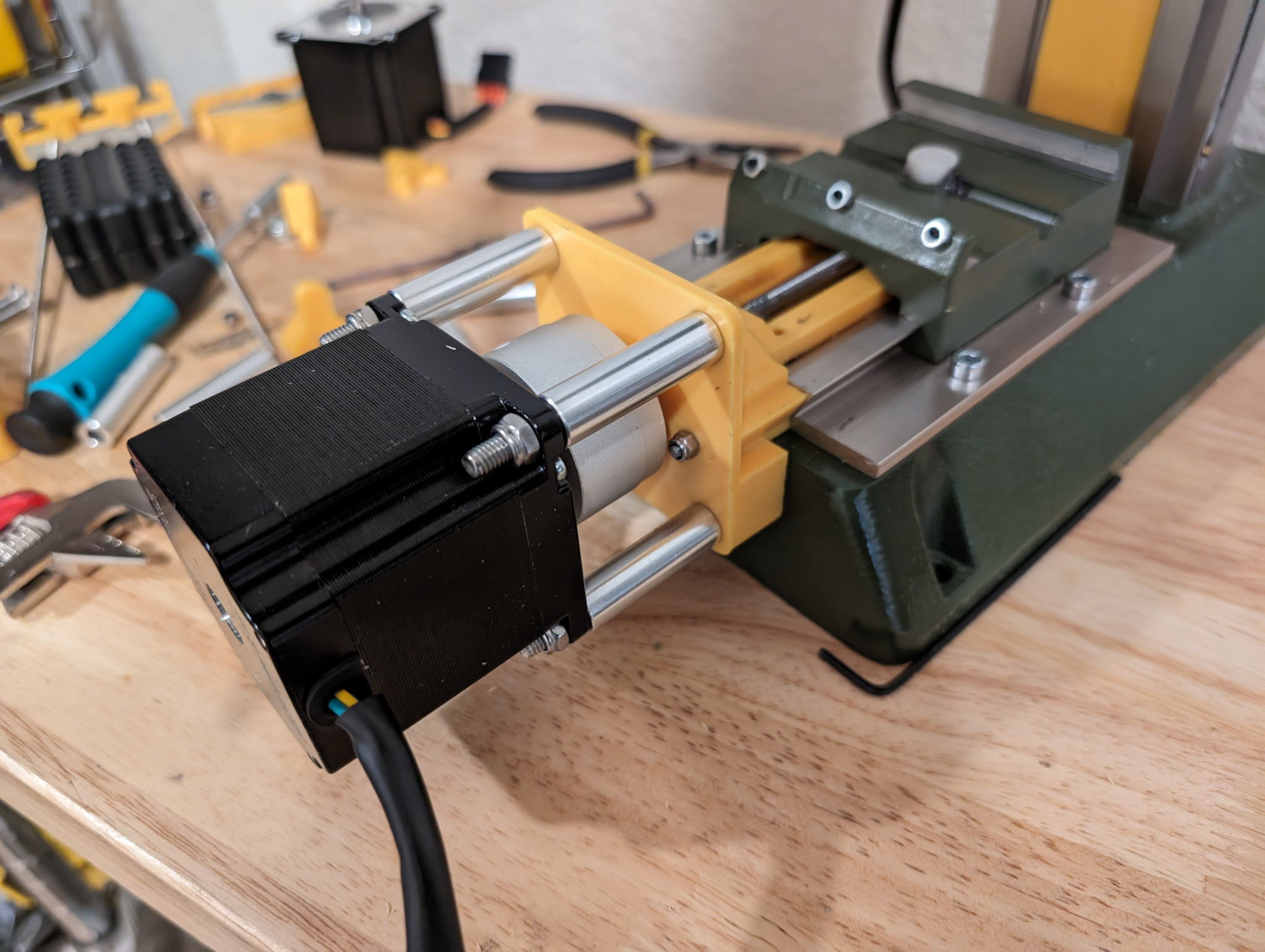
Install the Y axis shaft. On the front side there should be a ball bearing (which comes as a hamburger of 3 components) and a 5mm spacer, and the AliExpress coupler should be installed as shown. On the back side there should be a ball bearing and the (left-threaded) locknut. You will need blue Loctite even though it is a nylon locknut because there will not be enough thread to engage the nylon anymore after this modification.

Put the M5 countersunk screws in and entire Y axis back on the mill. Make sure to push the bottom against the cast iron before tightening so it is properly supported.

Install the stepper motor. Use cnc-stepper-nut-tool to help you, the lock nuts can be annoying.
Use the 120mm extra-long M3 drill bit to carefully drill out the 2.5mm channels to 3mm. Use plenty of machining oil and go slowly to avoid breaking the bit. (We will no longer use the self-tapping screws and instead put M3 threaded rods though these channels which will hold things much more securely.) Work the drill from both sides to get all the way through the channel.
Insert the original manufacturer's metal plates into the X axis parts. (I know, this is different from the Y axis; on the Y axis we discarded these plates but on the X axis we are going to use them.)

Fix them in place with two M3 threaded rods cut to length.

Install the lead screw. On the right side you have a 2mm spacer (I use 2 washers here, but avoid the practice of stacking washers if you can), a hamburger roller bearing, and the AliExrpess shaft coupler installed. On the left you have a hamburger roller bearing and the lock nut. Again you need Loctite because the screw threads will not be enough to engage the nylon.

Install the stepper motor. Use cnc-stepper-nut-tool to help you, the lock nuts can be annoying.

Remove thick plastic cover at base of the mill, which will give us additional clearance to the back of the mill.
Remove the 4 M3 screws on top of the Z axis. CAREFULLY turn until the cap and lead screw comes loose from the milling head, taking care not to drop the milling head.
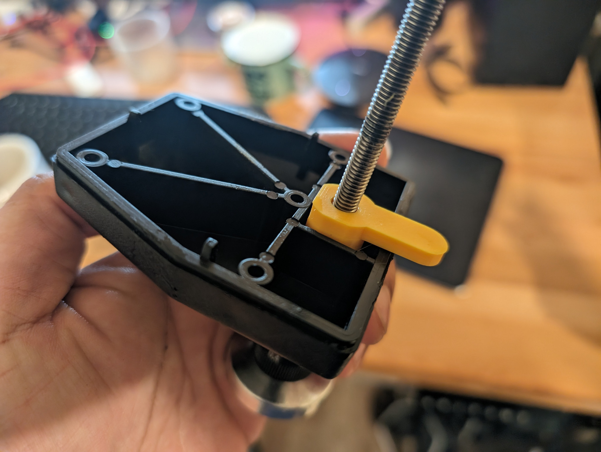
Proceed to remove the locknut that holds the Z axis lead screw in place. Use cnc-z-nut-tool to help you remove the lock nut that holds the Z axis lead screw in place.
Now reassemble the Z axis, using both parts A and B, and using two ball bearings, one on each side of the 3D printed parts.

Secure the lock nut in place. Tighten until there is no backlash but do not over-tighten. Again you can use the same cnc-z-nut-tool to help you.

Install the AliExpress shaft coupler and stepper motor as usual.

Install the Z axis back on with the head. Put 4 new M3 50mm long bolts to secure it (the original ones will be too short).

IMPORTANT! Insert this Z axis stop piece into the channel, which will stop the head before it falls out of the Z axis leadscrew. If you wish you can put a dot of adhesive to hold it in place, but it will hold itself behind the black plastic tab just fine.
Put the covers over the couplers to help prevent chips landing inside. They should snap in place.

Finished.
You can build an enclosure if you want. I highly recommend it.
