There are two separate stacks for the lane construction: one for clustering the lane points belonging to the same lane marking and another for grouping the lane points clusters that belong to the same lane. Firstly, on each lidar scan, we filter the road and non-road points, and then we employ an intensity-based approach to filter out the lane and non-lane points. In order to cluster the lane points belonging to the same lane marking, we need to convert the lane points from the base_link frame to the Odom frame. Once the newly scanned lidar points are in the Odom frame, we loop through them to determine which of the existing clusters in the first stack is closer. We have a threshold distance to determine a lane point that belongs to a cluster. If the distance between the new lane point and the nearest point from the closest cluster is less than one meter, the new lane point is added to this cluster. Otherwise, the new lane point will be added as a new cluster in the stack and increase other clusters' inactive count by 1. The inactive count is reset to zero when adding a new lane point.
We move a particular cluster into the second stack if the cluster's inactive count reaches the threshold limit, as shown in the below equation. It indicates that a particular cluster is not receiving any lane point for a while, suggesting that it has received all the lane points of a lane marking. $$\begin{Bmatrix}Move&inactive\ count > 20\ lidar\ scans\\Not\ move&otherwise\end{Bmatrix}$$ The threshold for inactive_count is selected by the trial and error method.
Before we move the lane marking clusters into the second stack, we convert them to line segments. In the second stack, line segments belong to the same lane grouped into one cluster. So, a cluster in the second stack can contain multiple line segments. When we add a new line segment to the second stack, we loop through all the clusters to determine the appropriate cluster where the line segment belongs. To do so, we first project the lastly added line segment in each cluster into the new line and then compute the Euclidean distance between the projected points and the first point of the new line segment. If the distance between the projected point of the closest cluster and the starting point of the new line segment is less than 0.25 m, then the line segment is placed to the nearest cluster. The below equation describes the merging criteria. A new cluster is formed with a new line segment and added to the second stack if existing clusters do not meet the merging criteria. $$\begin{Bmatrix}Merge&distance\ < 0.25\\Not\ merge&otherwise\end{Bmatrix}$$
We use a slope-intercept form of a line to compute the projected points of existing clusters. Firstly, we take the lastly added line segment from each cluster and compute its slope,
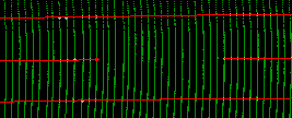
We found that 0.25 as a distance threshold fit through the experimentation in most cases as our focus is mainly on straight roads only. However, this threshold may vary with sharp curvy roads, but it can be tuned depending on the experiment. This whole process until the lidar scan finishes. In a nutshell, we construct the lines from the line segment, and the collection of adjacent lines forms the lane. The below Figure depicts the constructed lanes.

Due to intersection and missing lane markings, the initial result of the lane construction module may have broken lanes. For example, as shown in the below Figure, if the middle lane is broken, we make use of an intermediate representation called lanelets to complete them. The lanelet library has a vast amount of functions to deal with lanes. In order to utilise the capability, we first convert the lanes into lanelets format. In the lanelets, there are three essential elements: points, linestrings, and lanelets. The linestring is a collection of points, and each lanelet has the left and right linestrings. The road is then a collection of lanelets. In our experiment, we use a three-lane road. Then, we divide the entire road into twenty-five-meter sections, and the length of the lanelet is set as 25 meters. It indicates that, in each section of a three-lane road, three parallel lanelets are there. As we discussed, lanelets have two line strings, and adjacent lanelets share the linestring. So, in total, there are four linestrings for three lanelets. If the distance between two LineStrings is more than 5 meters, that indicates the missing lane. We create a linestring between existing LineStrings to fill the missing lane. We choose 5 meters based on the concept that a single lane has 3 meters width, and if the middle line is missing, then the width between two line strings will be more than 5 meters. The selection of 25 meters as the threshold distance for dividing the road is based on the trial and error method.
In OpenSCENARIO, we need to set the initial behaviour of the ego and adversary vehicle. There are a few components in OpenSCENARIO to describe the trajectory of the traffic participants. Firstly, the event is one of the main components to describe the lane change maneuver. The event consists of condition and action. For instance, cut-in and cut-out are events generated using the 'relative distance' condition to trigger and 'lane-change' action to create the maneuver. The
One of the OpenSCENARIO format's requirements is the reference to the OpenDRIVE file. The OpenDRIVE file defines the road network for generating the scenarios in simulation. In this work, we have employed an automatic OpenDRIVE file generation, compared to manual creation in other scenario generation methods.
We capture five parameters during the lane construction stage, as shown in the below Figure:

The OpenDRIVE file generation starts with the 'planView' element. It defines the shape of the road. As we create the road network section by section, we need to define the shape of each section. We use