dan.ellis@gmail.com 2023-10-08
See the full details and many more pictures on my blog post
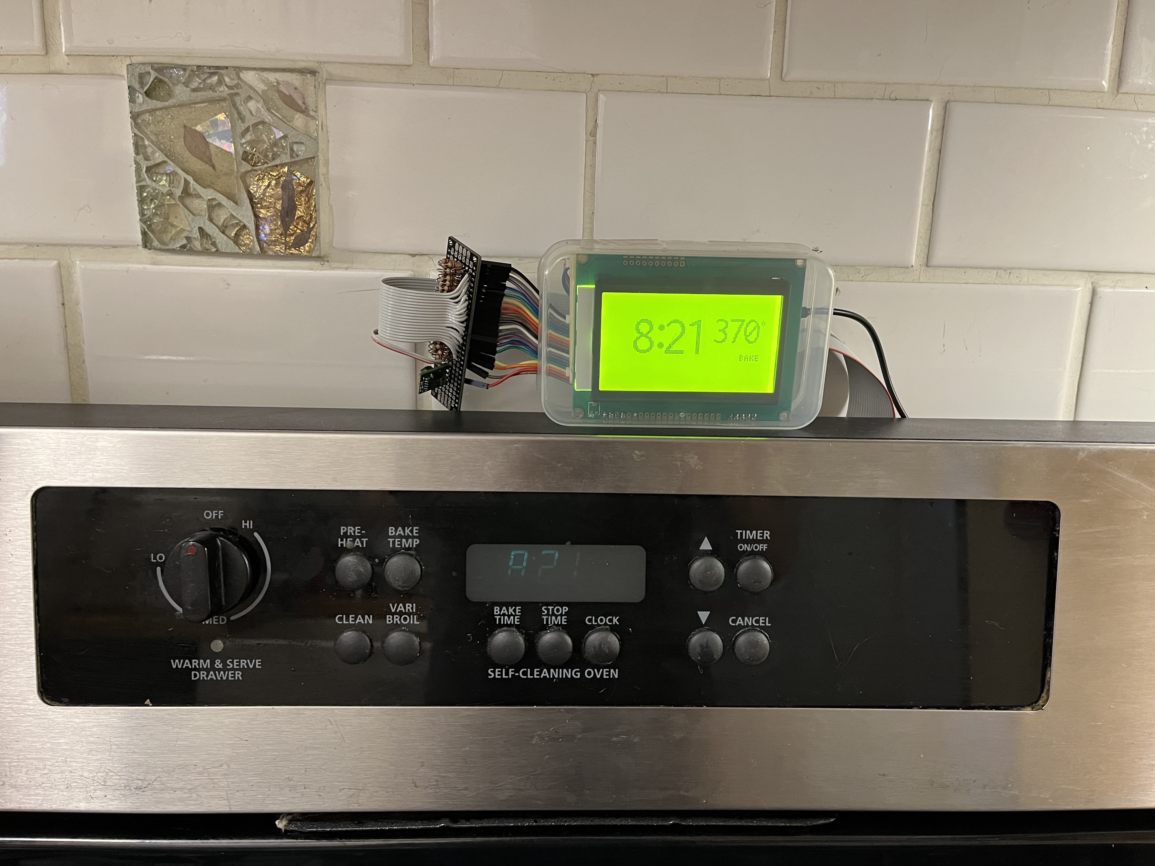
This code drives a substitute for a Vacuum Fluorescent Display (VFD) on my kitchen range that had become difficult to read with age (these displays typically begin to dim after 10 years or so). My solution is to mirror the intended VFD display on a separate 128 x 64 pixel backlit LCD display.
Passive external circuitry takes the grid and anode voltages from the VFB and drops/limits them to 0 and 3.3v, suitable for input to a 3.3v MCU. I'm using an RP2040 Pico because I need 18 input pins to read the 7 grids and 11 segment anodes that drive the VFD, then another 4 output pins to drive the ST7920 LCD display module that I'm using.
The VFD drive cycles between the 7 grid "regions" in the display, synchronously setting the 11 segment anode voltages. This code attaches an interrupt to each grid voltage; on the interrupt, it sets up a brief timer to wait for the anode voltages to stabilize. When that timer expires, the 11 anode (segment) pins are read in and stored, independently for each grid region. After reading the 7th grid, all the stored segment bits are copied to an output buffer.
The board cycles through the grids in about 4ms in 10 slots of ~400us (with ~380us positive pulses and ~20us gaps), so the sampling of the segment anodes is timed to be 100us after the grid interrupt. (7 grids are fit into 10 time slots by repeating the first 3 grids for two slots each; I'd expect this to make them brighter, but I never noticed this.)
These captured values are monitored by the foreground task. When a change is detected, the segment bits are interpreted and re-rendered on the LCD display. Each of the 4 clock digits and 3 temperature digits, which are 7-segment numeric displays on the original display are re-interpreted into the underlying digit (or "F", "-", and " ") and displayed as large glyphs roughly copying the original display. The remaining segments correspond to entire words in the original display ("BAKE", "TIME", etc.) and these are displayed in a small font, again roughly matching the original display.
Layout and pinout of the VFD: https://www.alibaba.com/product-detail/Futaba-MWO-Display-7-LT-91G_62527234028.html
Video revealing the display model number: https://www.youtube.com/watch?v=bSUa4f8KvhM
.. from the service (Nick's TV Repair) that will replace the dim displays: https://nickselectronics.com/products/318010100?variant=44698119340308
Forum thread discussing another user's experience with the same problems on the same oven / control panel: https://www.badcaps.net/forum/showthread.php?t=71797
Helpful article about the basics of VFD circuits: https://www.noritake-elec.com/technology/general-technical-information/vfd-operation
With an oscilloscope, I found that that the oven control board had a 12v supply for its logic, but the VFD had a -19V bias on its 3VAC cathode (filament) emitter. Then, the anode drives were approx +6V for "on" (same for grid and segment), and about -24V for "off". To map these down into 0 to 3.3V, I used 19 repetitions of this circuit:
 VFD Anode Drive  o----|>|----^v^v^v-----+-------o  RP2040 input pin
  -24 .. +6V         1N4148   12 Kohm    |            0 .. +3.3V
                      diode              >
                                 22 Kohm <
                                         >
                                         |
                                        ///