Usage
There are some test python files included in the tests directory that are provided as unit tests.
To launch the unit tests you need to launch blender from the command line with the -P command line option to execute a python script:
blender -P tests/hull_test_7.py
There is a render_tests.sh script that will run and render all the unit tests in the tests directory and produce a series of .png image files in the tests/output directory.
If you are able to generate these output images it's probably working correctly.
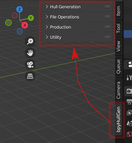
bpyhullgen has a sidebar panel tab user interface.
The user interface is divided into 4 sections:
- Hull Generation
- File Operations
- Production
- Utility

This section is for generating a hull design.
By clicking the GenHull button a default rectangle should be displayed as per the length and width defined. By default no chines exist so it is a square hull.
Some basic definitions:

This is the length of the hull in meters.
This is the width of the hull in meters.
Number of subdivisions for curve generation. For draft development keep this to a smaller number to keep things responsive and fast. For final output you can increase resolution as needed.
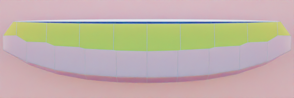
Multi chine hull resolution 5. Fast and responsive workflow.
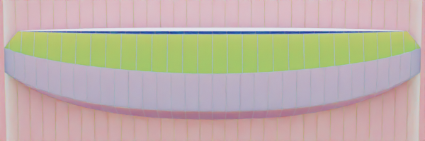
Multi chine hull resolution 16

Multi chine hull resolution 32

Resolution 64 Slow - probably more than you need...
This is the thickness of the material in MM. Bulkeads, keels, cutouts will all be this thickness.
3mm material

6mm material

18mm material
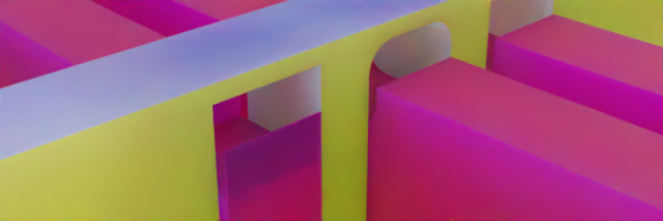
This is the amount of overcut for slots. If there is no overcut it is very difficult to assemble pieces after they are machined. The overcut is a ratio of material thickness to cut size. In the below image you see a profile view of a bulkhead with two keels. The one keel on the left has an overcut of 2.0 which means the cutout for the keel is 2.0 x (twice) the size of the keel. The keel thickness is 6mm (count 6 cubes) and the cutout has 3 on each side (3+3=6). So the overcut ratio is 2.0 x 6 or 12mm slot. To the right of the red line in the image the overcut is 1.1 or 1.1x 6mm = 6.6mm. The default overcut size is 1.1 which means 1.1 x material thickness for slots.


This is the amount of clearance on top of a slot in MM. For laser or water jet cutting this isn't so critical because the inside corners are cut more square. For CNC milling which often creates rounded inside corners because of milling bit circumference this figure needs to be tweaked depending on your cutting machine.
Slotgap 5mm - if middle keel is CNC cut with round edges on inside corners the model won't assemble correctly because the pieces overlap.

Slotgap 10mm - notice the middle keel round inside corners from CNC machine cut. Right keel is laser cut and has square edges on inside corners.
Slotgap 15mm exaggerated distance to highlight slotgap function.
Toggle to enable or disable generation of bulkhead items. On a complex model this can be disabled while focusing on tweaking other parts of the model to optimize generation speed.
Toggle to enable or disable generation of keel items. On a complex model this can be disabled while focusing on tweaking other parts of the model to optimize generation speed.
Toggle to enable or disable generation of longitudinal items. On a complex model this can be disabled while focusing on tweaking other parts of the model to optimize generation speed.
Toggle to hide the hull (exterior shell) after generation. If you are focusing on tweaking bulkheads, keels or longitudals you can hide the external hull after generation so you can focus on the other items. This is to streamline workflow.
Procedurally generates the hull and supporting structures.
Deletes all procedurally generated hull items.
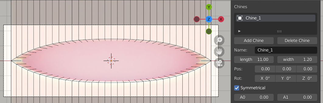
This allows you to add a chine definition to the hull generator. If you add a single chine the default name is Chine_1. Clicking GenHull again will regenerate the hull with the new chine.

By default a chine is symmetrical. Two chine curves are generated on the left and right side of the hull. By default the "chine cutter" curve is hidden. By searching in the outliner window you can find the chine curve and chine cutter used for boolean operations on the hull. They are hidden after generation by default.
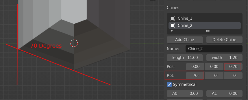 Same model with 2nd chine added - the chine is rotated 70 degrees and the position is shifted up (Z) 0.7m.

By adjusting the rotation and position of chines a hull shape can be developed.
By adjusting the parameters of each chine a hull shape can be developed.
A0 A1 values affect the curve endpoint inverse weight. Higher values cause the curve endpoint to resist movement towards center line.
A0 = 0, A1 = 0

A0 = 1, A1 = 0

A0 = 0.5, A1=0

A0=0.2, A1=0.4
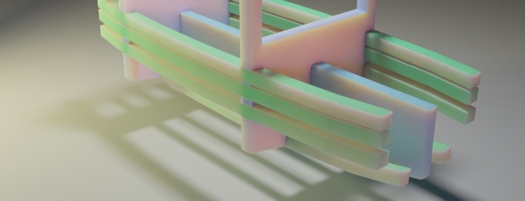
 Each chine has a
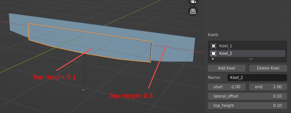
 core_offset parameter. The core_offset parameter affects the width of the bulkhead walls. In the above picture the top chine has a 0.1m core offset, upper side 0.15m, side 0.25m, bottom 0.4m. If you want the bottom of the bulkhead to have a flat floor instead of a V - you can adjust the bulkhead floor_height parameter to create a constant floor height instead of releative to hull curve.

In the above picture the red lines are controlled by core_offset and purple lines controlled by floor_height.
Floor height and core_offset work together to create a blended result. The core_offset will provide a minumum specified thickness for structural strength and floor_height will add onto this so the floor doesn't dip into a V. The final result will also depend on the chine curves that define the exterior of the hull.
A longitudinal is associated with a chine. You add a longitudinal after you have added a chine because it follows the chine curve. If you do not have any chines defined you cannot add a longitudinal.
A single chine can have multiple longitudinal items with different Z offset.
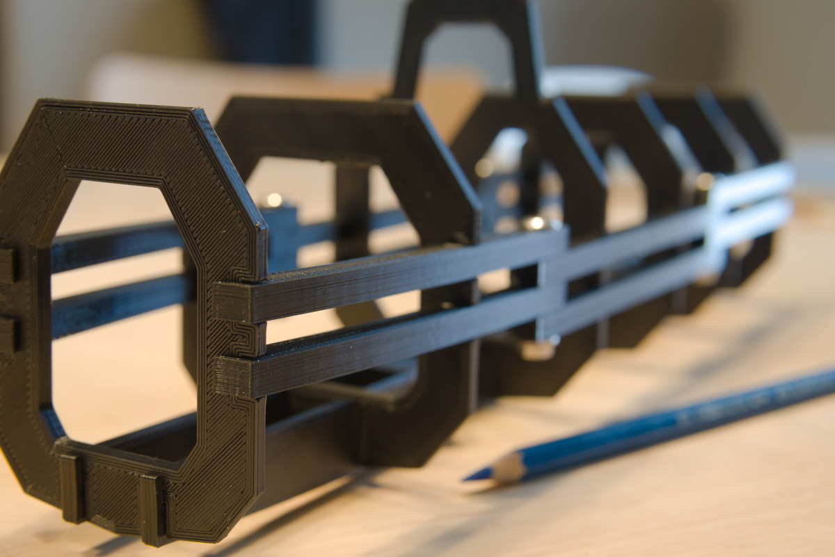
This allows you to add bulkhead definition to the hull generator.
 In the example picture there are 3 bulkheads defined.
Bulkheads can have fixed floor height so the floor is level inside the boat even though the bottom hull is curved. In the above picture the two bulkheads on the right have different floor heights.
This allows you to add a keel definition to the hull generator.

Refresh the list of saved files. The default path is /hull_models and is relative to the script installation directory. The script does not auto refresh file list. You should click refresh files if no files are shown. A future version may auto refresh on startup.
Create a new file to save the hull definition.
Saves the hull definition as an XML configuration file.
Saves the hull definition as an XML configuration file.
The production section of the UI has functions that are related to the manufacturing a design into a real physical object.

Iterates through all objects in scene and applies boolean modifiers in the modifier stack. A unique material with color value based on the hash value for each object name is generated and assigned to each face affected by each individual boolean modifier. Additional material slots will be created if necessary.
 For complex models this step can take a bit of time.
Separates an object by materials and renames each separated object to a useful name. Used in conjunction with ApplyAllBool which creates a useful name for each material based on the boolean cutter object which is cutting the base object. The renaming allows the resulting plates to inherit the name of the chine definition object which defined the boolean cut which makes everything more organized.
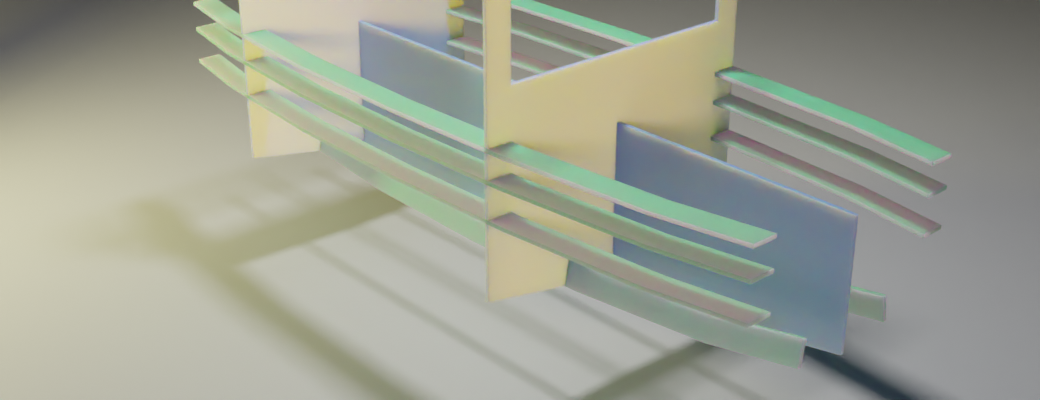
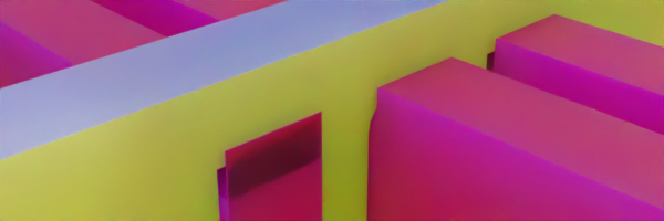
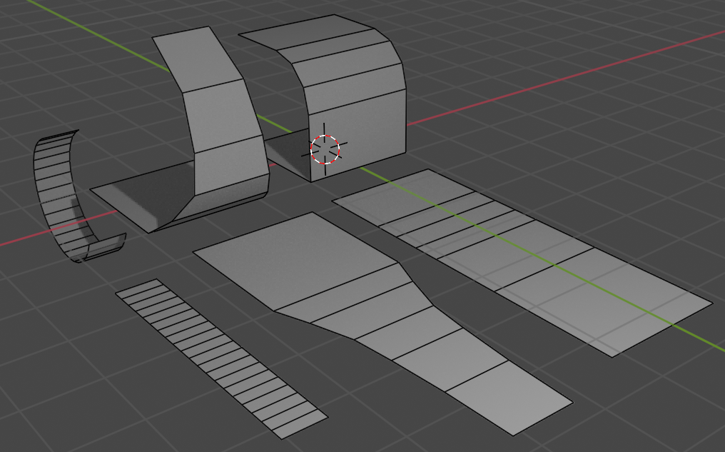
This function unfolds a curved mesh along edges so it's flat. This is needed for accurate CNC or laser material cutting. Most machine control programs prefer .DXF or other flat 2D design file.
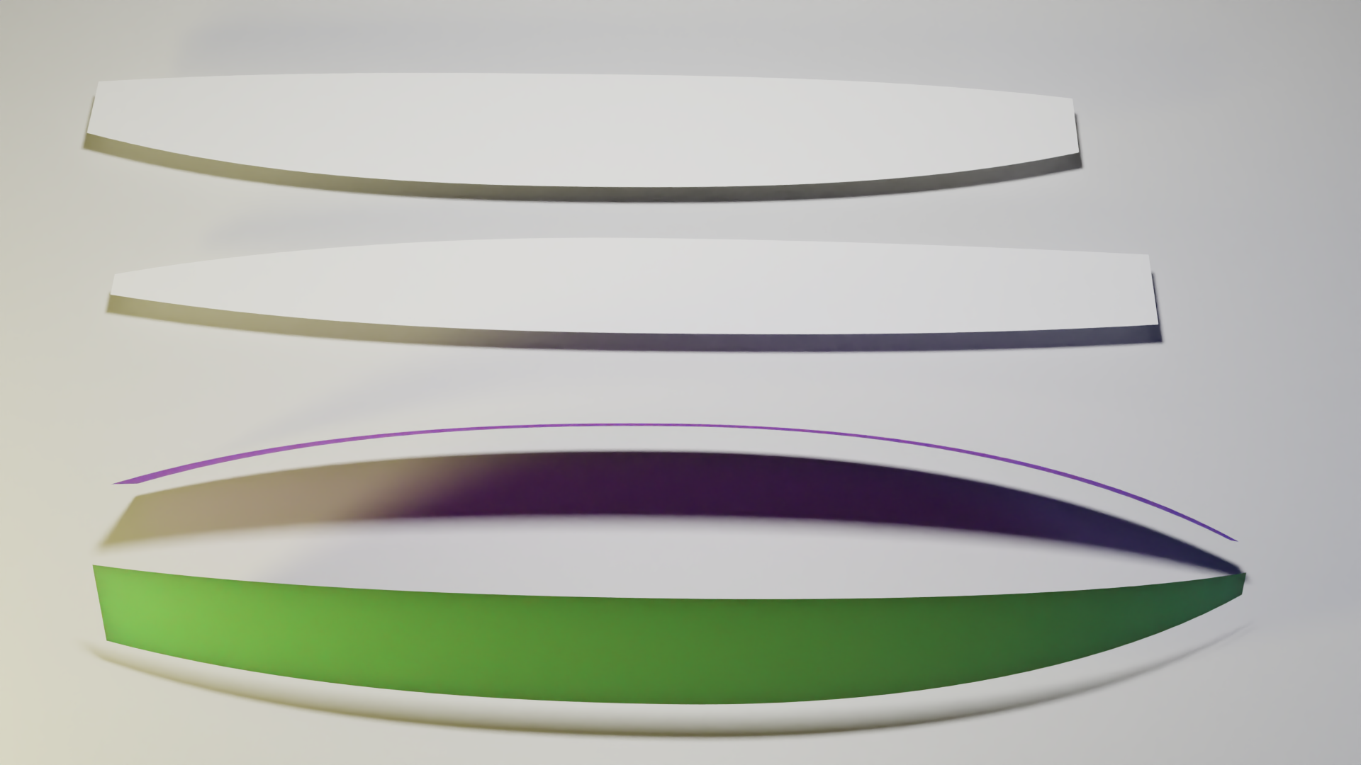
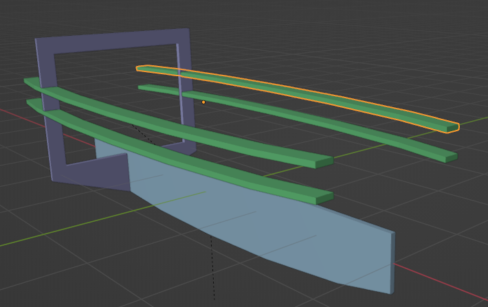
In the above example - the two white surfaces are generated from the green and purple boat chines. First select the objects to be flattened then click flatten. The generated objects are 2D with no depth so if you are in side view you may not see anything until you switch to wireframe or top view.
bpyhullgen is designed to ensure all chines and faces are developable surfaces so they will all flatten easily.
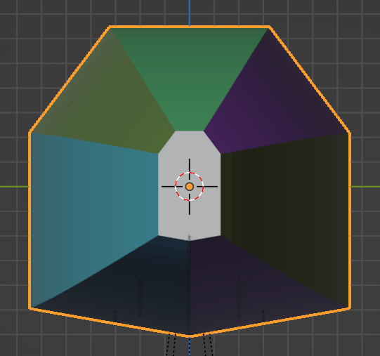
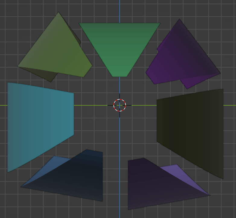
 This icosphere is not able to be flattened becuase cuts are required to unfold it correctly. bpyhullgen does not currently attempt to perform any cuts.
Flatten is designed to unfold shapes that do not require cutting.
Hollows out a mesh by deleting any edges that are not perimeter.
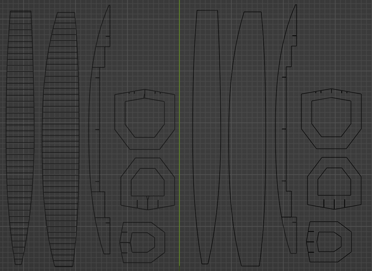
The left side of the green line has extra geometry that is not needed and will cause problems if you send these to a laser cutter because there are interior construction type lines that were used for the development of the surface but are not needed for production.
The right side of the green line is in the above picture is an exact copy of the shapes on the left side but the hollow operator has been applied and all the interior construction geometry has been removed. This is clean and ready to send for laser or CNC cutting.
When defining structural members they need to be solid objects to correctly create the cutouts in other structural members. When fabricating you need to flatten each object so it's a 2D representation. Plates are cleaned up by deleting faces that are not aligned to a specific normal direction. For example keel plates are cleaned by deleting all faces that are not facing to the left side. Forward Bulkheads are cleaned by deleting all faces not facing forward.
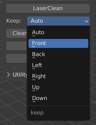
The following options are available to clean specific directions, Front, Back, Left, Right, Up, Down
The Auto option follows the following logic based on object name:
- Keel.* = Left
- Bulkhead. = Front
- cutterchine. = up
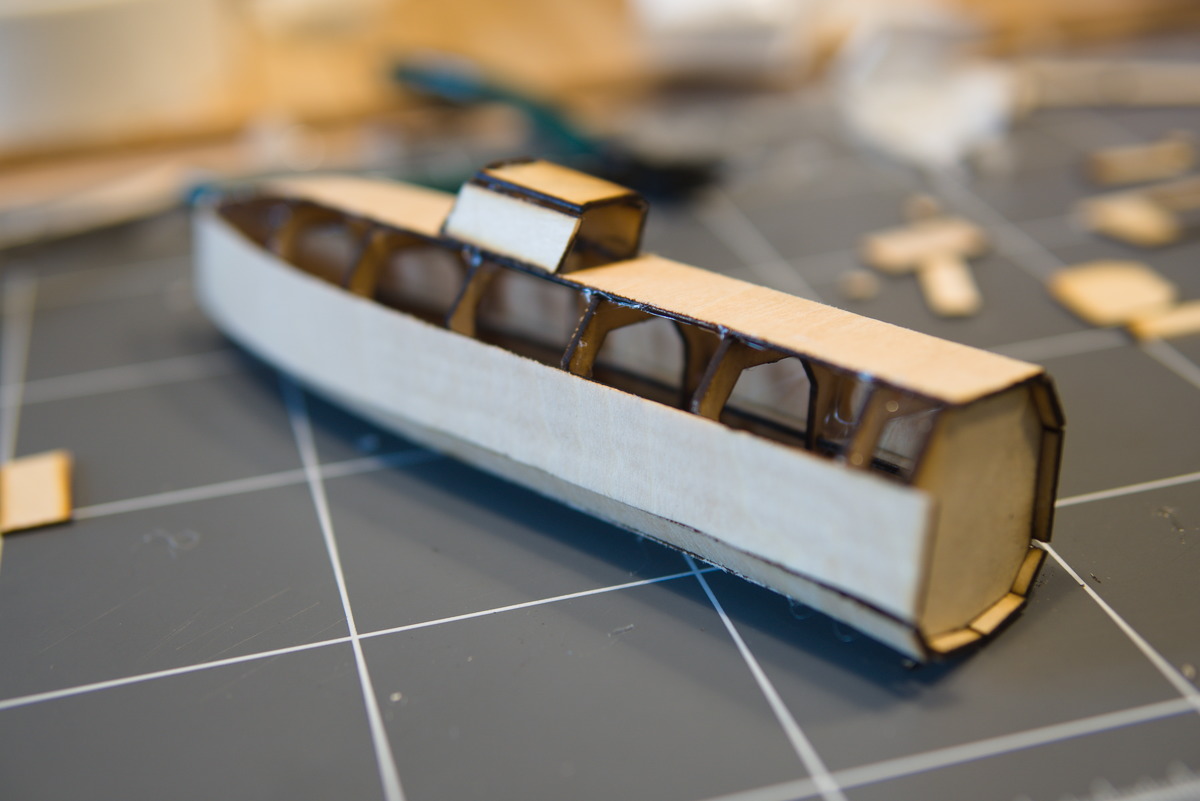
Here is an example profile view of the side of a hull and 3 bulkheads.

The bulkheads need to be flattened to create a 2D shape to accurately represent a cutting path for a cutting machine to cut 2D materials that are delivered in sheet surfaces.
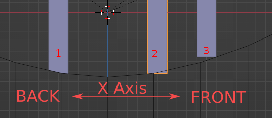
- Bulkhead 1 has not been flattened yet. The Back face should be preserved when flattening this object.
- Bulkhead 2 has been flattened by preserving the back face. This is incorrect and will cause the model to not fit together correctly during production.
- Bulkhead 3 has been flattened by preserving the forward face - this is correct and the pieces will fit together correctly during assembly.

The above picture shows the correct flattening of objects. Back, Front, Front. Bulkheads aft of the chine curve center should be filter back faces, and bulkheads forward of the chine curve center should be forward. In most cases the chine curve center is position 0. In the future the auto should be updated to handle this for now the auto does not work in all cases so manually selecting forward and aft bulkheads works best for now.
This function only operates on selected objects. Select the objects you wish to flatten and select FlattenFaces. You should first apply all booleans before trying this function.
ExportCSV exports the file hull_export.csv into the current working directory. The following fields are exported for each mesh object in the scene:
| Field | ||
|---|---|---|
| name | ||
| posX | surface_area | sizeX |
| posY | face_count | sizeY |
| posZ | volume | sizeZ |
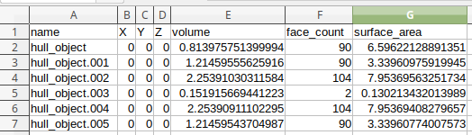
The output format is comma separated values.
### ExportPlates ImportPlates
These functions were removed. Previous versions used a process to export surfaces to .svg file using baked UV map process. Scaling errors were introduced and this was not the correct way. Now this has been replaced and simplified with flatten feature.
This function exports all currently selected objects to DXF format. I created a button to do this so I could consistently get the same results without having to tweak the options for DXF export.
One additional thing this function does is apply a default material to any objects that have no material assigned. I found that the DXF exporter would fail if an object has no material assigned so this goes through each object and makes sure at least a default material is assigned if no material exists in the objects material slots which is the default configuration.
Make sure you have DXF export blender addon enabled or this will fail. The DXF export blender addon is included in the default blender install.
The utility section of the UI contains tools that can be used for rendering or analysis.
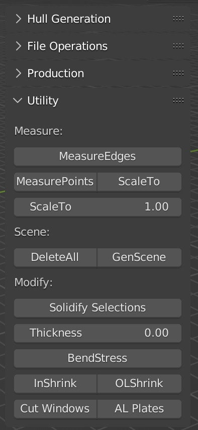
This measures the perimeter of selected 2D shapes. This is useful for calculating cut length of plates. Useful for calculating what the price will be to cut your plates.
Used to measure distance between two points in 3D space.
- Select an object
- Switch to edit mode
- Make sure you are in Vertex Selection mode
- Select TWO points (Vertex).
- Click MeasurePoints button The distance in 3D space between the two selected points will be displayed. This function is useful in conjunction with the ScaleTo function when scaling imported plates which were previously exported with the ExportPlates function.
Used to rescale all objects to a specific size (desired scale). This is usually used in conjunction with a reference object such as a default plane (2m square) so everything can be scaled to a specific size. When you ExportPlates the size is not preserved (UV mapping limitation). This step is necessary to rescale everything back to the correct size.
- Select an object
- Switch to edit mode
- Make sure you are in Vertex Selection mode
- Select TWO points (Vertex).
- Click ScaleTo button
The current distance between the two points will be measured and a scale factor will be calculated to determine how to scale ALL objects so the distance between the two selected points is exactly the distance specified in the ScaleTo textbox below the ScaleTo button.
Blender 2.8x uses Meters for the default unit and most laser cutter software importing DXF files use mm for default unit. After you determine the correct scale - scaling everything by 1000 works great.
Utility function to delete all objects in scene except Lights, Camera, and Empties. I found this function useful to start from scratch with procedurally generating objects from a script without having to select all, then unselect camera, light, and empties sometimes I use to track to a focus point before doing delete.

Generates a 40m x 80m x 40m background backdrop with curved corner for rendering. Utility function I created when deleting all objects and procedurally adding new ones sometimes I want a backdrop quickly.

Applies a solidify modifier with specified thickness to all selected objects. This is useful for quickly adding a thickness for rendering when you have many procedurally generated objects and don't want to add the modifier to each one.

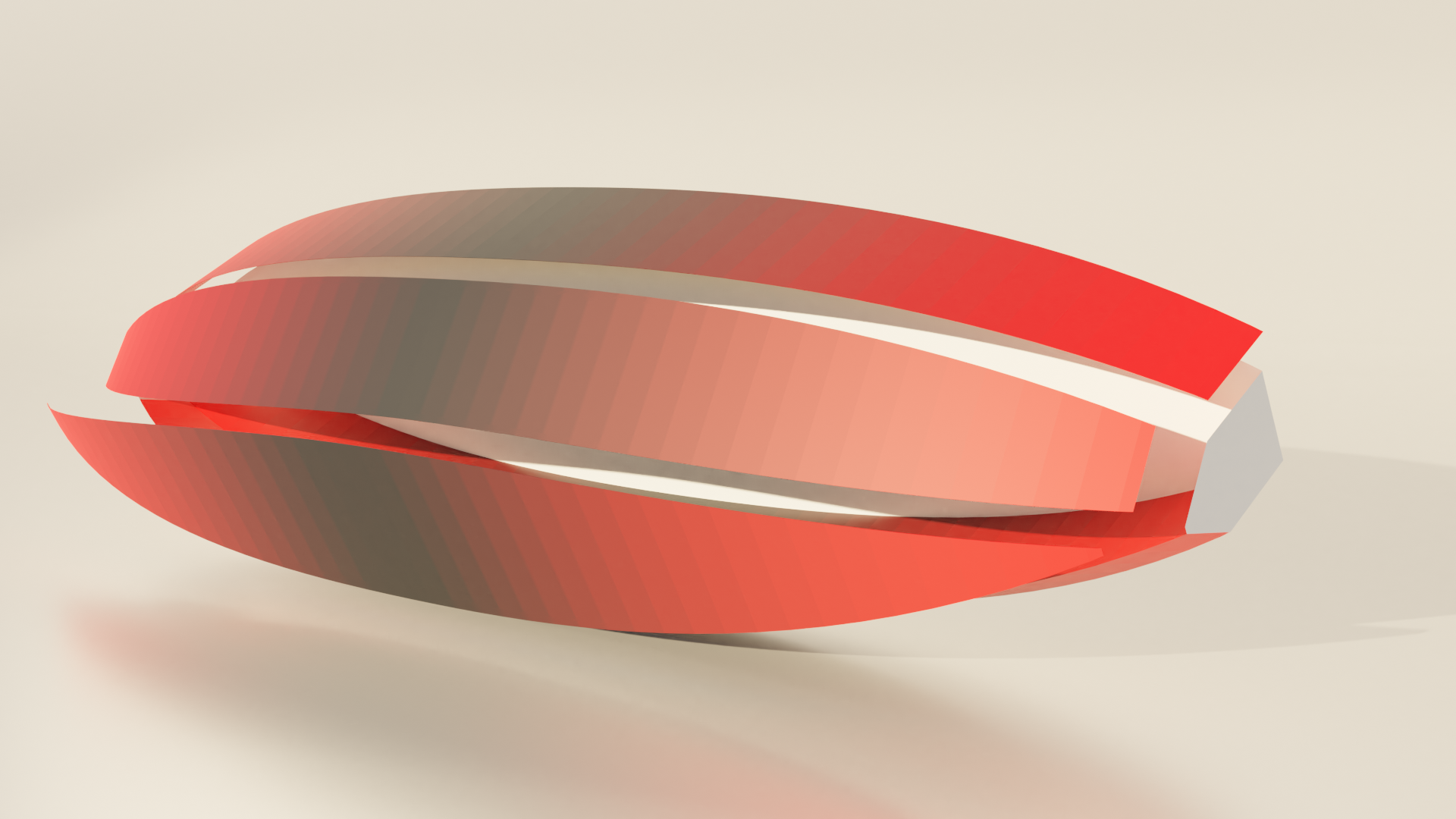
This feature is for analyzing the amount of bend stress on various parts of a plate. The angles between each face on selected objects (supports multiple selections) is measured and a color assigned to vertex group in relation to the bend angle between the faces. Blender internally has a "Mesh Analysis" feature that can be set to "Sharp" which will show the sharpness of edges but this only works in edit mode and only with objects that have thickness. Plates with no thickness don't seem to work. Also with the blender internal "Mesh Analysis - Sharp" you need to manually adjust the angle to "tune" it to the object you are trying to analyse with the min and max angle parameter. The bendstress feature of bpyhullgen bakes the angle ratios into the vertex color of each object so you can render it later and view bend stress on multiple objects at once. It also automatically calculates the min and max angles for all faces in the object so you can get maximum contrast visualization without having to tweak it. If the resolution of the curve on the plate is high resolution the angle between each face may be less than 1 degree (0.3 degrees or something like that) and it takes time to tune manually.
This function would be more useful if it displayed hard value calibrated bend values such as bend amount per Centimeter or bend amount per Meter. This enhancement could easily be added to what is here here now already as a foundation. Getting the code to procedurally measure face angles and assign bend angle derived vertex colors to a renderable material was the first step.
 When building smaller aluminum scale models I had to really push hard on the ends and I ended up building a jig to hold the bends in place prior to welding. I couldn't bend it by hand, it needed to be tortured. I remember thinking to myself next time I will find a way to analyze the bend amount so I know what I'm up against and where the critical bends are. That's how this function started.
You can see in this example BendStress plate analysis the tips of the side plates are the most bend in the whole design.
This function is currently under development so not documented yet.
Collapses all branches in the outliner hierarchy view. When lots of objects are created procedurally it gets really messy in the outliner. I couldn't find a way to do this through code before the window is displayed because the context was not correct so I added a button to do it manually.
Windows are created procedurally but no cuts for the windows are created in the hull until you call this function. This allows you to preserve the hull shape as a watertight mesh for other modeling purposes. This function calculates which hull plates intersect which windows and only adds boolean difference modifiers to cut the window hole to the hull places that actually intersect the window mesh object.
Procedurally creates an Aluminum looking material and assigns it to all Bulkheads, chines, keels, and support structures. When many objects are created procedurally it takes a long time to change material for all of them and this does it quickly.
If boolean modifiers are not applied sometimes results are not as expected.
Suggest run the ApplyAllBool operator
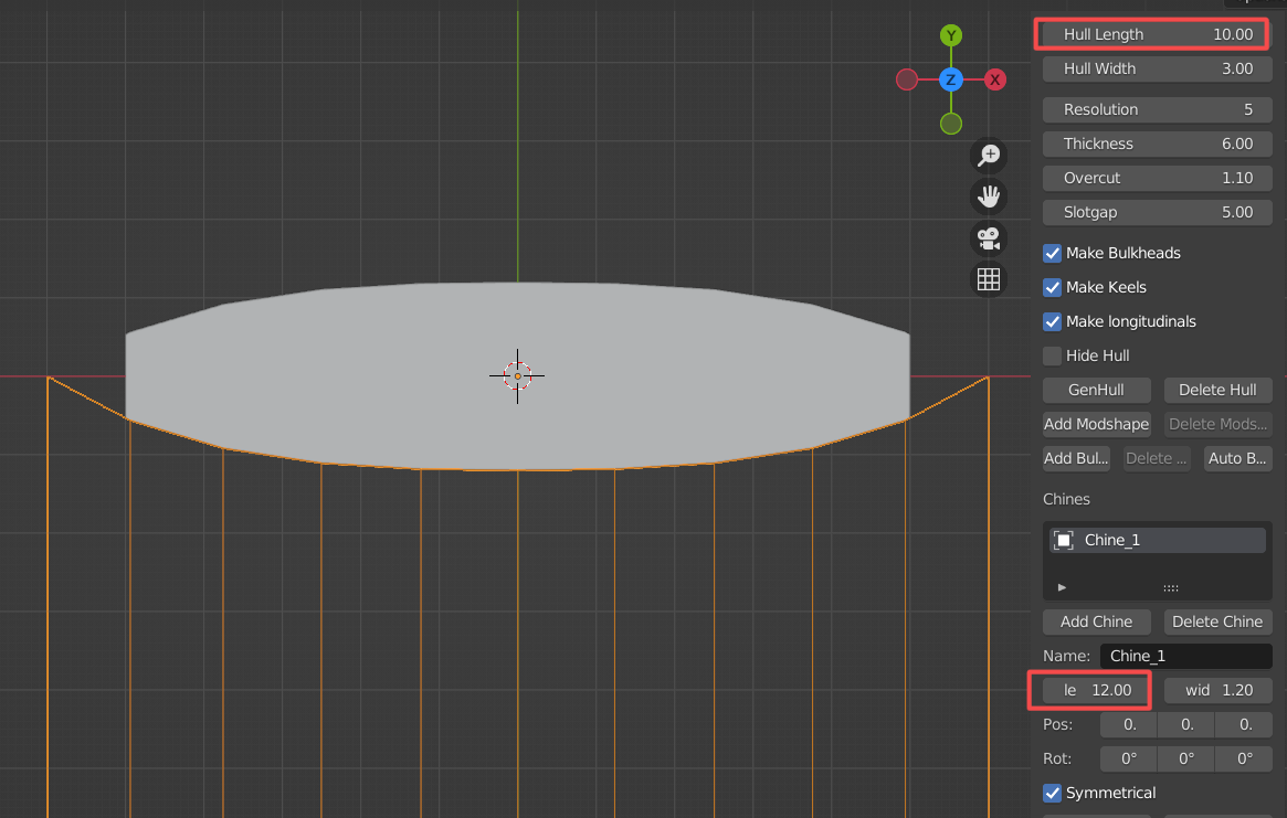
In this hull definition - the hull is 10 meters long but the chine curve is 12 meters long. This creates a square end on the hull.
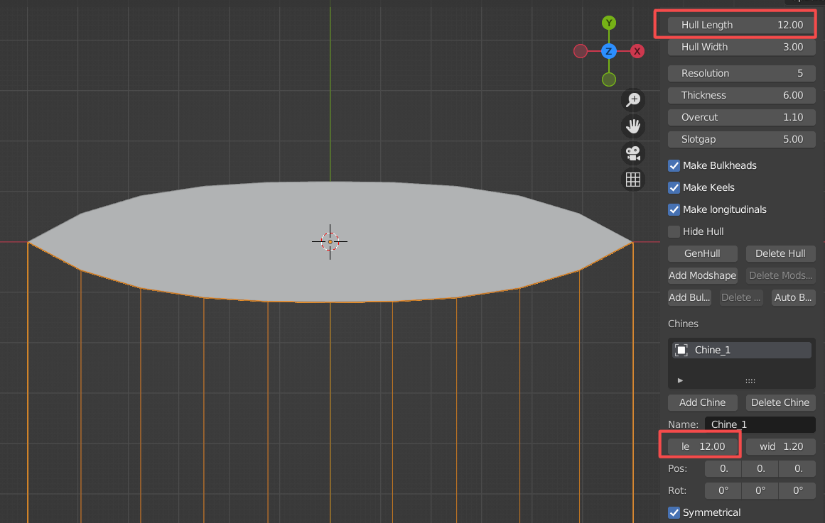
In this hull definition the hull length is 12 meters long and the chine curve is 12 meters long. A sharp point is on the end.
I have created square ends on some of my designs - it's easier to weld from the inside and simpler to fabricate in some circumstances when there is not a sharp end.