Skip to content
New issue

Have a question about this project? Sign up for a free GitHub account to open an issue and contact its maintainers and the community.

By clicking “Sign up for GitHub”, you agree to our terms of service and privacy statement. We’ll occasionally send you account related emails.

Already on GitHub? Sign in to your account

Several pzemac sensors do not work when connected to the same bus #1139

Closed
ASL07 opened this issue Apr 12, 2020 · 7 comments
Closed

Several pzemac sensors do not work when connected to the same bus #1139

ASL07 opened this issue Apr 12, 2020 · 7 comments

Comments

@ASL07
Copy link

ASL07 commented Apr 12, 2020

Operating environment/Installation (Hass.io/Docker/pip/etc.):

I'm using the Version: 1.15.0-dev but I have also tried this with the latest release

Board is Wemos d1
ESP8266
Affected component:

pzemac
https://esphome.io/components/sensor/pzemac.html
Description of problem:
Several pzemac sensors connected to the same uart bus, with different modbus adress for each sensor don't work

Problem-relevant YAML-configuration entries:

esphome:
  name: panel
  platform: ESP8266
  board: d1_mini

# Example configuration entry
uart:
  rx_pin: D1
  tx_pin: D2
  baud_rate: 9600
  stop_bits: 1

sensor:
  - platform: pzemac
    address: 1
    current:
      name: "Apartment 1 Current"
    voltage:
      # NOTE: Use this to force sending values even if they stay the same
      # force_update: true
      name: "Apartment 1 Voltage"
    power:
      name: "Apartment 1 Power"
    frequency:
      name: "Apartment 1 Frequency"
    power_factor:
      name: "Apartment 1 Power Factor"
    energy:
      name: "Apartment 1 Energy"
    update_interval: 30s

  - platform: pzemac
    address: 2
    current:
      name: "Apartment 2 Current"
    voltage:
      name: "Apartment 2 Voltage"
      # force_update: true
    power:
      name: "Apartment 2 Power"
    frequency:
      name: "Apartment 2 Frequency"
    power_factor:
      name: "Apartment 2 Power Factor"
    energy:
      name: "Apartment 2 Energy"
    update_interval: 30s

  - platform: pzemac
    address: 3
    current:
      name: "Apartment 3 Current"
    voltage:
      name: "Apartment 3 Voltage"
    power:
      name: "Apartment 3 Power"
    frequency:
      name: "Apartment 3 Frequency"
    power_factor:
      name: "Apartment 3 Power Factor"
    energy:
      name: "Apartment 3 Energy"
    update_interval: 30s

  - platform: pzemac
    address: 4
    current:
      name: "Apartment 4 Current"
    voltage:
      # force_update: true
      name: "Apartment 4 Voltage"
    power:
      name: "Apartment 4 Power"
    frequency:
      name: "Apartment 4 Frequency"
    power_factor:
      name: "Apartment 4 Power Factor"
    energy:
      name: "Apartment 4 Energy"
    update_interval: 30s

  - platform: pzemac
    address: 5
    current:
      name: "Apartment 5 Current"
    voltage:
      force_update: true
      name: "Apartment 5 Voltage"
    power:
      name: "Apartment 5 Power"
    frequency:
      name: "Apartment 5 Frequency"
    power_factor:
      name: "Apartment 5 Power Factor"
    energy:
      name: "Apartment 5 Energy"
    update_interval: 30s

  - platform: pzemac
    address: 6
    current:
      name: "Apartment 6 Current"
    voltage:
      force_update: true
      name: "Apartment 6 Voltage"
    power:
      name: "Apartment 6 Power"
    frequency:
      name: "Apartment 6 Frequency"
    power_factor:
      name: "Apartment 6 Power Factor"
    energy:
      name: "Apartment 6 Energy"
    update_interval: 10s

  - platform: pzemac
    address: 7
    current:
      name: "Apartment 7 Current"
    voltage:
      # force_update: true
      name: "Apartment 7 Voltage"
    power:
      name: "Apartment 7 Power"
    frequency:
      name: "Apartment 7 Frequency"
    power_factor:
      name: "Apartment 7 Power Factor"
    energy:
      name: "Apartment 7 Energy"
    update_interval: 30s

Logs (if applicable):


Additional information and things you've tried:

I have several pzemac sensor connected to the same uart (using pins D1 and D2), I am using a Wemos D1
Each of the pzem has a different modbus address
The pzem are wired in parallel to the Wemos D1 through a level converter 3.3v to 5v
I have tried using an external supply for the pzem bus, suspecting the wemos could not provide enough power, but it makes no difference

I have tested all the pzem individually, and they work well, whenever there is only one device in the bus
However, when I connect more than one pzem to the bus, it doesn't work, the Wemos doesn't boot up properly, and, both the TX and RX leds on the pzem are on continuously.

Has anyone had any success with a similar setup?

@randybb
Copy link

randybb commented Apr 12, 2020

But it doesn't belongs here (better place are discord or HA forum) as it is not SW problem, just your HW issue. I have 3 of them on one bus and no issues with the latest dev release. Sure, a small modification is needed - you need add protection diodes and pull-up resistor. Opto-couplers will work on 3,3 V as well, but if you want to have nice, then you need replace two resistors on each device. Here is my schematic (top: original for 5 V, modified for 3,3 V, and then my interconnect module with resistor and diodes):
opto

@ASL07
Copy link
Author

ASL07 commented Apr 12, 2020

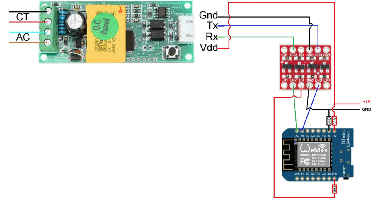
Thanks for your schematic.

I have posted it here because I was not sure wether my hardware setup was wrong, or it was a software issue.

In my case, I am working at 5V voltage, because I am using a 3V3 to 5V level shifter, so I don't need to modify the pzem resistors.

I have a setup similar to this, but with several pzem wired in parallel (all sharing the same level shifter)

image

Could you explain why protection diodes and pullup resistor are needed for connecting more than one modbus slave to the bus?

It was my understanding that just wiring all the devices in parallel was enough.

@randybb
Copy link

randybb commented Apr 12, 2020

You can check arendst/Tasmota#2315 - they have similar schematics. Diodes are used as protection for the transistor inside of opto-couplers and the pull-up resistor is just a good practice to have input HI in default state and then the opto-couplers will drive it to ground (LO). You can achieve the same with integrated pull-up that can enable your MCU/SoC on input pin.

@stale
Copy link

stale bot commented Aug 10, 2020

This issue has been automatically marked as stale because it has not had recent activity. It will be closed if no further activity occurs. Thank you for your contributions.

@stale stale bot added the stale label Aug 10, 2020
@ipetrovits
Copy link

ipetrovits commented Aug 11, 2020

I have a setup similar to this, but with several pzem wired in parallel (all sharing the same level shifter)

image

Hi, I built a similar setup and never worked.. I ended up dropping the level shifter out and instead of replacing resistors, just added 470ohm ones in parallel resulting in 319ohm. Then diodes and pull-up resistor, everything worked from then.
By the way if this is your real schematic, then you missed to add 5V to the HV pin of the level shifter. Also measure resistance because it is possible that your level shifter has the pull-up built in.

@probot-esphome
Copy link

pzemac source
pzemac issues
pzemac recent changes
(message by IssueLinks)

@stale
Copy link

stale bot commented Dec 9, 2020

This issue has been automatically marked as stale because it has not had recent activity. It will be closed if no further activity occurs. Thank you for your contributions.

@stale stale bot added the stale label Dec 9, 2020
@stale stale bot closed this as completed Dec 23, 2020
@github-actions github-actions bot locked and limited conversation to collaborators Oct 25, 2021
Sign up for free to subscribe to this conversation on GitHub. Already have an account? Sign in.
Projects
None yet
Development

No branches or pull requests

4 participants