Skip to content
New issue

Have a question about this project? Sign up for a free GitHub account to open an issue and contact its maintainers and the community.

By clicking “Sign up for GitHub”, you agree to our terms of service and privacy statement. We’ll occasionally send you account related emails.

Already on GitHub? Sign in to your account

Adding support for PZEM004T energy monitor for 3 phase - request #2315

Closed
roblad opened this issue Apr 1, 2018 · 297 comments
Closed

Adding support for PZEM004T energy monitor for 3 phase - request #2315

roblad opened this issue Apr 1, 2018 · 297 comments
Labels
enhancement Type - Enhancement that will be worked on fixed Result - The work on the issue has ended

Comments

@roblad
Copy link

roblad commented Apr 1, 2018

Hi,

Is it possible add USE_PZEM004T and add support for PZEM004T Energy monitor for 3 phase by using
USE_SERIAL_BRIDGE and report each phase through that functionality ? May be there is possibility to use 3 phase config for USE_PZEM004T as it is in that project:

https://github.com/apreb/eNode

@roblad
Copy link
Author

roblad commented Apr 13, 2018

Hi,

Is it possible to add 3 PZEM004T in one node?

Rgds,
RL

@0x3333
Copy link

0x3333 commented Apr 26, 2018

I'm looking for the same thing.

As long as I can tell, each PZEM004T can be directly addressed, so you can hookup as many PZEM004T as you can in the same UART, when you read, you send the "ip address" of each module.

But the code in xdrv_03_energy.ino is not able to read from multiple sources. When I get my units I'll work on this. Don't know if this can be accomplished, but would be great.

@roblad
Copy link
Author

roblad commented Apr 26, 2018

Hi,
It means that when I change IP for each PZM and plug 3 of themas a 3 soft serials or plug 3 of them to 1 serial ? Could you sent me a private mesage if you could with more detailed manual or some code that you hook haw it looks. I am not such expert as you it will be very usfull :-)

Thanks,

@0x3333
Copy link

0x3333 commented Apr 26, 2018

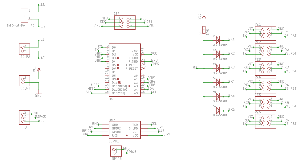
I mean plugging all the 3 PZEM in the same hardware/soft serial, like this:

smms_ttl

The diode can be a BAT45, the pullup resistor can be a 10K to 5V.

But you need to program the PZEM address before using this method, the address can be sequential, like 0.0.0.1,0.0.0.2,0.0.0.3, it is not really a IP address.

But the tasmota must be changed to accommodate multiple meters, you can test using an arduino.

@roblad
Copy link
Author

roblad commented Apr 26, 2018

Hi,

Many thanks, but I have a question, may be stupid, Master UART means tasmota serial ? Yes ?

And all of the slaves there are PZEMs Am I right ?

Have you got it on your Arduino/ESP connected ?

I will try it ofcource but first of all I am working for MQTT bridge through serial bridge of Tasmota - I have Nodes based on it:

https://github.com/artekw/sensnodetx

and receiver basenode which prints output to serial as JSON, I am working on www displaing all recaived data as normal sensors pluged to tasmota, next one task will be the hook of PZM004 ino.

and

also see that:

https://github.com/apreb/eNode/issues/1#issuecomment-354369777

@0x3333
Copy link

0x3333 commented Apr 26, 2018

Yes, Tasmota master, PZEM slaves. Yes, connected to ESP.

@roblad
Copy link
Author

roblad commented Apr 26, 2018

Hi,

Could you share Your ino code for PEZM for further testing, I have 3 already :-) after 2 months shipment :-) ?

@0x3333
Copy link

0x3333 commented Apr 27, 2018

Well, I don't have it actually, but here is some to start with:

#include <PZEM004T.h>

PZEM004T pzem(10, 11);

IPAddress ip[3];

void setup() {
  Serial.begin(9600);

  ip[0] = IPAddress(0, 0, 0, 1);
  ip[1] = IPAddress(0, 0, 0, 2);
  ip[2] = IPAddress(0, 0, 0, 3);
}

void loop() {
  for (uint8_t j ; j < 3 ; j++) {
    Serial.print("ID: ");
    Serial.print(j);
    Serial.print(": ");
    float v = pzem.voltage(ip[j]);
    if (v < 0.0)
      v = 0.0;
    Serial.print(v);
    Serial.print("V; ");

    float i = pzem.current(ip[j]);
    if (i >= 0.0) {
      Serial.print(i);
      Serial.print("A; ");
    }

    float p = pzem.power(ip[j]);
    if (p >= 0.0) {
      Serial.print(p);
      Serial.print("W; ");
    }

    float e = pzem.energy(ip[j]);
    if (e >= 0.0) {
      Serial.print(e);
      Serial.print("Wh; ");
    }
    Serial.println();
  }

  delay(1000);
}

Remember to call pzem.setAddress(ip[X]); with only one connected to set it's internal address.

@roblad
Copy link
Author

roblad commented Apr 27, 2018

Hi,

Many thanks, but what do you mean 👍
Remember to call pzem.setAddress(ip[X]); with only one connected to set it's internal address.

I did not catch you, it means that I have to set the pzem.setAddress(ip[X]) step by step with plug only one PZEM for initial setup of IP ? And next plug all of them for finale mastering am I right ?
What about Save set values in PZEM, will they disappear after power lost ?
What do you mean "with only one connected to set it's internal address"

@0x3333
Copy link

0x3333 commented Apr 28, 2018

Buddy, dont get me wrong, but you should do your homework...

Each PZEM have an Address. You must set a unique address to each one, individually. That's what I meant with setAddress. Create another sketch to set the addresses. Then run the one I provided.

@roblad
Copy link
Author

roblad commented Apr 28, 2018

Hi,

" but you should do your homework" yes I will :-), thanks for explanation, I let you know about my results :-)

@0x3333
Copy link

0x3333 commented Apr 29, 2018

Great, as soon as I get my sonoffs, I'll let you know my findings.

@asking23
Copy link

Any updates ? but in this way we would never be able to poll 3 Phases Simultaneously to Make Graph/Trend 3 Phases. Each Consecutive reading will have 1 Second Interval so wont be able to correlate voltage on each phase to each other.

@0x3333
Copy link

0x3333 commented May 29, 2018

I'm looking to do the readings in the same time slice. But I'll need to change the code. I'm on vacations now, next week I'll work on it.

@0x3333
Copy link

0x3333 commented Jun 12, 2018

Here I'm again. I read the code and believe that create another xdrv for this is the best option to me. Change a code that is shared with other devices to add 2 more phases will require a lot of effort and will not benefit the others. I'm looking to create a xdrv_13_energy_3phases.ino driver, especifically to PZEM004T, this way it will not add more line of codes to other energy meters and increased complexity.

I've only an hour at night to work on side projects, but will give it some attention.

@arendst , do you believe that this is the right thing to do? What is your direction on this matter?

Thanks!

@roblad
Copy link
Author

roblad commented Jun 12, 2018

Hi,

Where is xdrv_13_energy_3phases.ino ?

@0x3333
Copy link

0x3333 commented Jun 12, 2018

There is no xdrv_13_energy_3phases.ino, I'm about to write it.

@roblad
Copy link
Author

roblad commented Jun 12, 2018

aaaaaaa :-)

@stale
Copy link

stale bot commented Jul 27, 2018

This issue has been automatically marked as stale because it has not had recent activity. It will be closed if no further activity occurs. Thank you for your contributions.

@stale stale bot added the stale Action - Issue left behind - Used by the BOT to call for attention label Jul 27, 2018
@0x3333
Copy link

0x3333 commented Jul 27, 2018

Well, I changed to ESPurna, and in that firmware, it's simply not possible, it is too slow to read all magnitudes from all sensors. I'm working in a custom board with an Arduino Pro Mini that will read all PZEM(Max 6 devices) and will communicate using I2C, all measurements will be read in a single call. I'll let you know the progress.

@stale stale bot removed the stale Action - Issue left behind - Used by the BOT to call for attention label Jul 27, 2018
@rt400
Copy link
Contributor

rt400 commented Aug 21, 2018

any new with this ?

@0x3333
Copy link

0x3333 commented Aug 21, 2018

I'm finishing the custom board, the board will read up to 6 PZEM004T and will communicate using I2C/SPI. It constantly read the PZEM and buffer the responses, when asked the response is instantaneous. In my board I also added a ESP-01 module, so I don't need a Sonoff Basic or alike. But it is not finished yet...

screen shot 2018-08-21 at 11 07 35

screen shot 2018-08-21 at 11 07 50

@0x3333
Copy link

0x3333 commented Aug 21, 2018

Probably I will use this repo: https://github.com/0x3333/powermeter

But the code probably will change...

@rt400
Copy link
Contributor

rt400 commented Aug 21, 2018

https://github.com/apreb/eNode
did you see this ?
its looks that he success to do that..
can you share the diagram of connection ?
and i understant that you connect directly to wemos or arduino board ..so why use also in spi or i2c ?

@0x3333
Copy link

0x3333 commented Aug 21, 2018

Yes, I saw that.

In my case, the arduino pro mini(Not running arduino) is connected to a ESP-01(Running Espurna, but can work with any other firmware) using a spi connection. The arduino is only doing the hard work.

@roblad
Copy link
Author

roblad commented Aug 21, 2018

Hi,

Great, but will you add that to tasmota as a 3 phase module ?

@0x3333
Copy link

0x3333 commented Aug 21, 2018

Sure, @arendst will need to approve a custom driver, but sure.

@Jabol86
Copy link

Jabol86 commented Jan 7, 2021

@TrDA-hab

I created this )

PZEM004-2
PZEM004-3

And i made this project 100% open to all.
https://github.com/TrDA-hab/Projects/tree/master/PZEM%2BESP-01S

There would be no option to buy a ready-made soldered plate?

@blackscreener
Copy link

blackscreener commented Feb 18, 2021

With proper v3 1k mod PZEM need 3V voltage to get working. For pull up I need 3,3V or 5V ?? Why do you use 5V pull up with 3.3V logic ?
obraz

@IamStadam
Copy link

With proper v3 1k mod PZEM need 3V voltage to get working. For pull up I need 3,3V or 5V ?? Why do you use 5V pull up with 3.3V logic ?
obraz

I gave 3,3 without any mods. It works great for a year or so.

@blackscreener
Copy link

I gave 3,3 without any mods. It works great for a year or so.

This is the (proper) Way:
proper connection
Works even without pull up.

@ahmaddxb
Copy link

ahmaddxb commented Sep 6, 2021

Is 1N60, 1N60P diode compatable? I have it working with them currently but was trying to compare the datasheet with a bat54ws and dont really know about diodes.

I got some BAT54WS diode but they are smd type and cant really use them in my application.

Would be good to know if 1N60, 1N60P diode can do the job.

@ahmaddxb
Copy link

ahmaddxb commented Sep 6, 2021

Any reason why reactive power is not the same on all. Right now in the testing phase and just using one phase connected to 3 devices and all load clamp on the same load.

image

Edit:
I swapped round devices address it seams the same one will read reactive power only. Dont know if that one device is wrong or if the other 2 are wrong. Is there a known load that should read reactive power I can test?

Edit2:
Testing with a 13w led buld they all read reactive power now!!! The previous result I was using a hair dryer at full speed as the load. Anyone know why this would happen?

image

Edit3:
Moving the clamp from the device which has the reactive power to another also move the reactive load reading to the new device, so its clamp causing this.

@ascillato2
Copy link
Collaborator

Split Total Energy is supported now.

Docs: https://tasmota.github.io/docs/Commands/#setoption128

  • Command SetOption128 1 to enable split total energy results
  • Commands EnergyTotal<phase>, EnergyToday<phase> and EnergyYesterday<phase> to (re)set energy values

Issues: #13030 , #6160
Commit: d3fc03d

@barbudor
Copy link
Contributor

barbudor commented Nov 2, 2021

Split Total Energy is supported now.

Docs: https://tasmota.github.io/docs/Commands/#setoption128

  • Command SetOption128 1 to enable split total energy results

So128 is Http API
SO129 is split energy

@grappini
Copy link

grappini commented Nov 19, 2021

Any reason why reactive power is not the same on all. Right now in the testing phase and just using one phase connected to 3 devices and all load clamp on the same load.

image

Edit: I swapped round devices address it seams the same one will read reactive power only. Dont know if that one device is wrong or if the other 2 are wrong. Is there a known load that should read reactive power I can test?

Edit2: Testing with a 13w led buld they all read reactive power now!!! The previous result I was using a hair dryer at full speed as the load. Anyone know why this would happen?

image

Edit3: Moving the clamp from the device which has the reactive power to another also move the reactive load reading to the new device, so its clamp causing this.

After reading all the content from this topic i am confused. What wiring diagram did you use to make it work ?

Did you add every pzem module like this ( ModuleAddress x) without changing pzem address with factory software ?

ModuleAddress Set the address of a PZEM module1..3 = the last octet of the PZEM-004T serial address = the last octet of the address on MODBUS PZEM energy monitoring modulesPrior to setting the module address, the PZEM must be connected to both RX and TX, and AC voltage.Connect one PZEM at a time and issue this command. Repeat for each PZEM to be connected for multi-phase monitoring.The command without an argument cannot be used to read the address of the connected PZEM.

@arendst
Copy link
Owner

arendst commented Nov 19, 2021

  • First learn the difference between active, reactive and apparent power.
  • Then use a resistive load to measure active power while reactive and capacitive power will be zero.
  • Then conclude your one PZEM device is faulty as Tasmota is just representing the values read from your PZEM's. It doesn't do anything with the values provided by the PZEM.

@grappini
Copy link

Sorry Theo but i was asking about the correct wiring diagram of the pzems to theESP 8266 and how to add them to Tasmota.

@barbudor
Copy link
Contributor

@grappini so don't uselessly quote previous message

There is a how-to in Github Discussion where everything is explained with diagrams and commands

@grappini
Copy link

Sorry , i'm not so familiar with github interface , i'll not quote again long messages. I know how to connect 1 pzem with esp8266 but i can't find any diagram for connecting 2 or 3 pzems to one esp 8266.

@blackscreener
Copy link

@grappini
Check my post.

@grappini
Copy link

grappini commented Nov 24, 2021

Thanks @blackscreener for trying to help me.

@barbudor
Copy link
Contributor

So looking for a way to connect PZEM 17 that are RS485 in a topic dedicated to PZEM 004 that are RS232/TTL...... Doesn't sound good idea.
Now people coming to this thread will have confusing diagrams for PZEM 004.
I would suggest that now you have experience, you share it in a nice PZEM 17 how-to guide which make it clear and easy to find.

@grappini
Copy link

grappini commented Nov 24, 2021

I apologize for the confusion , i thought pzem 004 is also RS485. I'm using pzem 016 and 017 for my aplications.
I would like to connect multiple pzem 016 for 3 phase monitoring and in the future multiple pzem 017 for dc.
For the correctness of the information i will remove the wrong info from previous post.

@IerwinDE
Copy link

I have a device set up as described in this thread, running three PZEM 004 on 3 Phases and it has been working fine for over a year.
I recently got interested and Photovoltaics and would be really interested in the Total Energy per Phase.
Would it be possible to calculate the kWh for each phase seperately?

@sfromis
Copy link
Contributor

sfromis commented Aug 29, 2022

SetOption129 exists as a recent feature for "split total energy results", but I have no experience with PZEM devices.

@IerwinDE
Copy link

thanks a lot, upgrading to the latest versio of tasmota and setting Option129 worked like a charm

@Hambinex
Copy link

Trying to make 3-phase work using ESP32 C3.
One phase works fine, but when trying ModuleAddress 1/2/3 the device reports "done", but on the OSCILLOSCOPE I cannot see any communication after issuing the command. The communication simply silences for a while, then every second reading from PZEM module is restored. Can someone give me a hint? Thanks.

@barbudor
Copy link
Contributor

Did you configured each PZEM on its separated address one after the other, with onely 1 PZEM connected at a time to the ESP ?

@Hambinex
Copy link

Yes, one PZEM connected, but after issuing the command, the serial interface silences. Normal serial communication (reading of the power values) resumes after 5-6 seconds. It is like something is blocking the sending of the command to PZEM. Using the standard RX, TX of the ESP32 C3 module.

@phmllr
Copy link

phmllr commented Feb 4, 2023

hey folks
i got an problem with the PZEM and the ESP.
I followed different setups for this 3-phase solution an tasmota first shows me all 3 phases. But after a few seconds the third phase disapears and after another few seconds the second phase disapears too.
Then there are only the values for 1 phase are displayed and switching after everey 5 seconds between values showing only 0 an the last value that was measured. Via MQTT i wanted to read all values but they are static and dondt change anymore.

did anyone else got this problem?

@barbudor
Copy link
Contributor

barbudor commented Feb 4, 2023

@phmll
I suggest you open a new discussion and provide more details on your setup (not just "I followed the doc")

  • backlog template; module; gpio all
  • How you setup the 3 PZEM
  • logs with weblog 3

Thanks

@andy75andreas
Copy link

Hello,
is it possible to connect 4 PZEM to an ESP32?
I have 3x PZEM16 via an RX (the circuit with the diodes) that goes great.
Now I wanted to capture another consumer and need another additional PZEM.
The TX line have all 4 together.
The RX line is divided into 3x on RX and 1x extra RX1.

Is that possible?

@barbudor
Copy link
Contributor

barbudor commented Feb 4, 2023

You can have up to 8 phases on an ESP32 so that should be possible to extend the system to 4 but with using an additional RX pin, still use the same pin and have the PZEM on address 1, 2, 3 and 4

I can't tell for sure but that seems possible
Would need to be tested

@temasnick
Copy link

Can anyone succesfully setup 3 PZEMs with "wemos s2 mini" I tried everything (with diodes and 10k pullup, 3.3v with 1k resistor hack or 5v) but it is working only with one PZEM.

@bltoby
Copy link

bltoby commented Jun 4, 2023

Can anyone succesfully setup 3 PZEMs with "wemos s2 mini" I tried everything (with diodes and 10k pullup, 3.3v with 1k resistor hack or 5v) but it is working only with one PZEM.

Hi, I couldn't make even one working.
So I'm so "glad" to see you can get one PEZM-004T work with WEMOS S2 mini. How is your wiring and configuration?

@ThinkoMatej
Copy link

ThinkoMatej commented Sep 25, 2023

D1 mini Tasmota V13 no pullup resistor, BAT85 diodes , 1K resistor on Pzem 5V.

Sign up for free to join this conversation on GitHub. Already have an account? Sign in to comment
Labels
enhancement Type - Enhancement that will be worked on fixed Result - The work on the issue has ended
Projects
None yet
Development

No branches or pull requests