Wrover-kit SPI not working SD0-3 CLK #7465
Comments
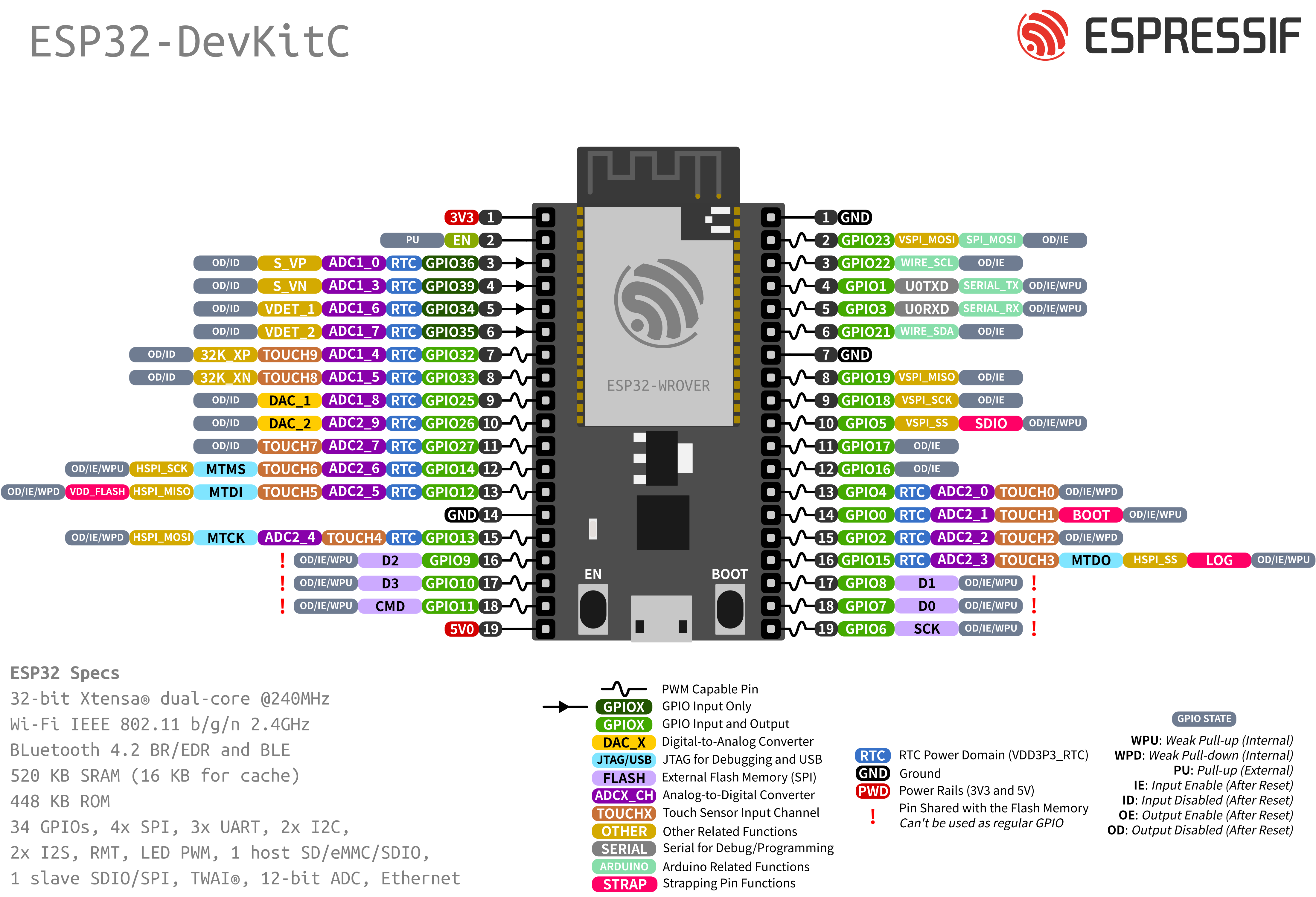
Can you link us to that description? You can not use those pins for SPI. You need to use any of the other pins. Default GPIOs for SPI are found here: |
|
Oh I did not see this diagram interesting! Here's the link: And then bellow is mentioned that:
Here's what I got when using the mentioned pins: It seems better but I see that the NSS pin is not working the right way for example. I was wondering also, could I use any other free GPIO other than GPIO5 right? Because GPIO5 is used to interface with the LCD (backlight). Or should I use a dedicated alternate CS? |


|
You can use whatever SPI pins you may need. SS is the CS pin. Yes, you can change it to any other PIN. |
|
Update: I realized that I flipped the logic analyzer connector. I still have issue but now I know that SPI is working. I'm using the following pins as me-no-dev said: |
|
What is the issue? I understood that SPI is working fine. |
|
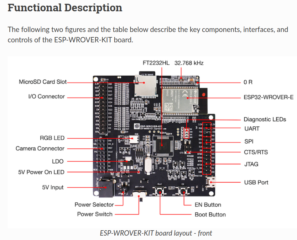
Yes it is working fine but the documentation is inaccurate I think. They mention pins SD0 SD1 SD2 SD3 CLK being SPI peripherals that we can use when in fact they are not. It should be mentioned in the ESP-WROVER-KIT DOC that it's the other Pins. and maybe mention where are the HSPI pins exactly. I'm referring to this page: and this picture |

|
Are you talking about this link? It is just saying that the SPI FLASH JP2 exposes these pins. If your application is running code from IRAM, it could, in theory, use those pins for something else... but this is really more advanced usage. By other hand, if the ESP32 is set to use DIO FLASH mode, the pins 9 and 10 (SD2 and SD3) will be always free for any other purpose. |
|
It could be interesting to maybe mention that it is more advanced usage? And if possible mention the readily usable SPI pins in the doc which are : |
|
A PR https://github.com/espressif/esp-idf/pull/10356/files is pushed in order to make the document clearer regarding not using JP2 Flash SPI pins. |
Actually, it is possible to use any free GPIO for MISO, MOSI, CLK and CS for Arduino SPI. |
|
Merged changes to the documentation in
|

Board
ESP-WROVER-KIT V4.1
Device Description
wrover-kit connected to LoRa Module SX1262
Hardware Configuration
SD0 connected to MISO of sx1262
SD1 connected to MOSI of sx1262
GPIO5 connected to NSS of SX1262
CLK connected to CLK of sx1262
GPIO27 connected to RST of sx1262
GPIO36 connected to BUSY of sx1262
GPIO26 connected to DIO1 of sx1262
Version
latest master (checkout manually)
IDE Name
Arduino IDE
Operating System
Ubuntu 22.04
Flash frequency
80 Mhz
PSRAM enabled
yes
Upload speed
921600
Description
I'm currently trying to use ESP-WROVER-KIT and interface it with a LoRa SX1262 by using the RadioLib library.
In the description of the board, they say I can use CLK,SD0,SD1,SD2,SD3 for SPI and choose any free GPIO for chip select.
I'm not sure who is MISO, MOSI out of all these SD0-3 pins. I also tried to run SX126x_Transmit example. I get the error that no device was found (error -2)
Also, I tried using my Logic Analyzer Logic 8 Saleae and even the SCK pin is flat..
Sketch
Debug Message
Other Steps to Reproduce
n/a
I have checked existing issues, online documentation and the Troubleshooting Guide
The text was updated successfully, but these errors were encountered: