Turbidity
This is a recipe for a turbidity sensor - which detects the particulate matter content in water, and thus a measurement of pollution. This can be be done fairly simply by recording how occluded a light source becomes as water passes through a tube to prevent outside light from entering. For most scientific uses, relative measurements are sufficient: e.g. so a comparison can then be made with clear water.
- Cable: 4 core 0.14mm 26AWG (£15.29 for 50 m) - thin and flexible to avoid breakage, but not too thin!
- Heat shrink 2.4mm (£1.50 for 1.2m)
- Heat shrink 6.4mm (£2.43 for 1.2m)
- White Clear Lens 3mm LED 3000mcd 20mA (£0.35)
- Light Dependent Resistor (LDR) 8k-24k at 10 lux. 1M dark resistance. 5mm diameter. (£0.34)
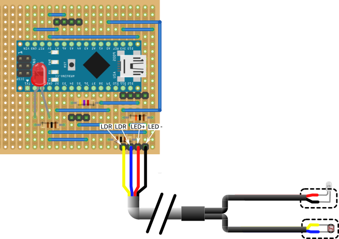
We need to make a cable that will be resistant to wear and underwater usage:
- Cut 3-4m of cable
- Strip ~12cm of outer insulator to expose 4 insulated wires
- Cut 2x 10 cm pieces of thin heat shrink and heat over two pairs of wires
- Cut 1x 3cm fat heat shrink and cover the join for extra strength

- Bend pins on LDR and LED at right angles close to package, cut short - remembering LED positive (long leg)/negative (short leg)
- Cut wires as close to heat shrink as possible and solder LDR and LED. Later we need to encapsulate everything including the start of the heat shrink in resin to fully waterproof everything, so the neater this can be done the easier it will be!

- Test both before the next step as this will save a lot of time if they are not working! You can test the LDR with a multimeter (shielding from light and see if it responds) and the LED by using a 100Ω resistor and the 3.3V supply from the Raspberry Pi.
The electronic components are waterproofed using resin, cast in a simple home-made mold.
- Plasticine (e.g. https://www.hobbycraft.co.uk/newplast-white-modelling-clay-500g/569572-1007) [£3.50]
- PVA mould release agent (e.g. this) [£3.47]
- Resin (we used this resin and hardener, mixed together in a 10(resin):3(hardener) ratio) [£10] TOTAL APPROX COST = £16.97
- Make 2 blocks of plasticine, about 2.5cm wide, 3cm long and 1.5cm deep. Then use a scalpel to cut a rectangular hole in each block, about 1 cm wide, 2cm long and 1 cm deep. Cut a small slot at one end for the cable to fit through. They should look something like this:

-
Use a paintbrush to coat the inside of the blocks with PVA release agent, leave to dry. Re-coat it 3-4 times until there is a thick blue coat. This can take a couple of days including drying time, depending on the weather and warmth. Make sure it is absolutely dry before proceeding.
-
Place the LED in one plasticine mold and the LDR in the other, with the light/sensor facing up and the cable sitting in the slot. Press some extra plasticine into the slot to hold the cable in place.
-
Mix resin according to instructions (to reduce the bubbles, mix very slowly and keep everything warm), then pour slowly into the molds. The plastic of the LED should be just poking out of the resin, and the LDR should be just below the surface of the resin. Leave to dry for 72 hours. See the image below.
-
Pull away the plasticine and pull/scrape off the blue PVA layer - you should be left with the components encased in two small solid blocks of resin, looking like the right hand part of the image below.

Making the housing
The main housing is essentially a tube, that is as light proof as possible. For a cheap version, cut a ~25cm length of ~4cm diameter black plumbing pipe. For a more expensive version, laser sinter 3D print one of these, and two of these from matt black plastic (if using Shapeways, it's called Black Natural Versatile Plastic). The more expensive version has end caps that can be siliconed into place, to block further light and reduce the amount of debris entering the tube - it also has a fin to help keep the orientation in the water, and attachment holes for straps. If you have a basic printer, there are other versions of the tube and end caps that are better suited to extrusion printers here and here - we print using an Ender 3D Pro, which is a printer that costs about the same as buying a set of these prints from Shapeways...
The cost of this will vary hugely, from ~£2 if you are using plumbing pipe to ~£212 if you use Shapeways to print the tube and end caps, and maybe £5-10 max if you print it yourself.
- Tubular nylon webbing, 2.5cm wide, 3m long (e.g. https://www.profabrics.co.uk/products/tubular-webbing-25mm?variant=5940866755) [£1.95]
- Nylon webbing (not tubular), 2.5cm wide, 32cm long (e.g. https://www.profabrics.co.uk/products/tubular-webbing-25mm?variant=5940866755) [72p]
- Velcro (both fluffy and hooked sides), 2.5cm wide, 2m long (e.g. https://www.profabrics.co.uk/products/sew-on-velcro-25mm?variant=5940923267) [£3.32]
- Wood dowel, 9mm diameter, 185cm long (e.g. https://www.wickes.co.uk/Wickes-Light-Hardwood-Dowel-Moulding---9mm-x-9mm-x-2-4m/p/121225) [£2.88]
- Polyester thread, e.g this which is recycled. [£1.95] TOTAL APPROX COST: £10.82
- Cut an 80cm length of tubular webbing, a 30cm length of the hooked side of velcro, and an 8cm length of the fluffy side of velcro. Use a match to melt the ends of the tubular webbing so it doesn't fray. Place the pieces on top of each other such that the fluffy velcro piece is on top (with the fluff upwards), the tubular webbing is in the middle, and the hooked velcro is on the bottom (with the hooks upwards). The alignment of the pieces is shown below. Stitch the three pieces together strongly (3 times along each edge) - this is a thick piece so it can help to tack them together first, and you'll probably need a modern sewing machine to get through it. Repeat this 2 more times so you end up with 3 pieces of webbing with velcro attached to each - these are the main straps that go around the turbidity sensor tube, and the velcro secures the straps to the tube.

- Cut a 35cm length of both the hooked and fluffy sides of velcro. Stick the velcro together, and overlap it by 2-3cm with the other end of the tubular webbing - see image below for the alignment. Stitch the three pieces together strongly. Repeat this 2 more times so you end up with 3 pieces of webbing with velcro attached to each end - this completes the main straps that go around the turbidity sensor tube, and the velcro just added secures the straps to the kayak handle.

-
Cut 2 x 70cm and 3 x 15cm pieces of 6mm diameter wood dowel or any other solid material (e.g. plastic or non-rusting metal) - shown in the image below.
-
Line the 3 main straps up parallel to each other, and in line with the holes on the 3D printed turbidity tube, or your piece of plumbing tube. Cut 3 x 18cm pieces of tubular webbing and melt one end of each piece to stop fraying, don't melt the other end yet - these are the cross pieces. Line your three cross pieces up perpendicular to your three main straps, at roughly equal distances along the length of the main straps - see below:

-
Stitch the melted end of each cross strap to the first of the main straps, in one straight line close to the melted edge of the cross strap (as shown by the top three yellow lines in the image below).
-
Now attach the middle of each cross strap to the middle main strap - you need to be able to pass a piece of wood dowel through the cross straps, so sew a straight line at the top and bottom of each cross strap to secure it in place (as shown by the middle set of six yellow lines in the image below).
-
Insert 1 short piece of wood dowel into each of the cross straps (this is where the webbing being tubular comes in!). Now that the dowel is in the webbing tube, melt the other end of the cross strap to stop it fraying. Stitch each cross strap to the third main strap, in one straight line close to the melted end of the cross strap (as shown by the bottom three yellow lines in the image below). The dowel should now be secured within the tube.
-
Cut 4 x 8cm pieces of plain webbing. Melt each end of each piece to stop fraying. Fold each piece in half to form a loop, with the melted ends together. Attach these at equal distances along the outer edge of one of the main straps, stitching a single line close to the outer edge of the main strap (as shown in red on the image below). These are to hold the cables.
-
Cut a small hole in the top end of each of the outer main straps (location marked in blue on the image below), but make sure you only go through one side of the tubular webbing. Hold each hole open and melt around the edges to stop it fraying. Slide the long pieces of dowel into the main strap tubing. The straps are now complete!

- 1-2 packs of black Sugru (https://sugru.com/buy/original-formula-black-3-pack) [£7.99]
- Silicone sealant (transparent e.g. https://www.wickes.co.uk/UniBond-Anti-Mould-Kitchen-and-Bathroom-Sealant-Translucent---274g%0D%0A/p/147508) [£10]
- Small cable ties if you're using plumbing pipe instead of the 3D printed tube [pennies, buy a pack of 100 as listed elsewhere] TOTAL APPROX COST: £17.99
-
Drill one small hole in each rectangular recess of the 3D printed tube (or just in the piece of plumbing tube if that is what you are using) located so that when you put the resin blocks into the recesses, the LED pokes through one hole, and the LDR is aligned with the other hole (if you are using plumbing pipe, make the holes half way along the length of the pipe, and at right angles to each other).
-
Fix the resin blocks into the recesses using sugru, making sure the LED and LDR are aligned with the holes, and the sugru doesn't go over them. Squidge a little sugru into any gaps around the edges to secure it further, and begin to block out light. Temporarily tape the resin blocks in place while the sugru dries.
-
Once the sugru has dried, either cover the backs and sides of the resin blocks with more black sugru to block out the light, or use a matt black waterproof paint to do the same job. Leave this to dry.
-
Use the velcro straps (the straps that are different lengths to each other, on the end furthest from where you poked the dowel through the holes) to wrap around the 3D printed tube, passing the long piece of velcro through the slots on the bottom of the tube, and making sure they are tight around the tube before sticking the velcro together. If you are using plumbing pipe, do the same thing, but you might also want to drill one or two small holes in the pipe to cable tie the outer straps in place so they don't slip off.
-
Apply a bead of silicone sealant around the ends of the 3D printed tube, and put the end caps in - once it dries, the silicone will stop them falling out but can easily be removed later if you need to clean inside the tube. If you're using plumbing pipe, don't worry about this step (the end caps help to stop debris entering the tube, and to block out light - if necessary, you can use any sort of mesh, fixed with an elastic band).
-
Pass the end of the cable up and through the small tabs on the side of the outermost strap, then it can be passed through the rectangular cable gland into the main electronics box.