Arduino emulation of the KENBAK-1
This is an Arduino-based emulation of the KENBAK-1, considered by some to be the first "personal computer". It was first advertised for sale in the September 1971 issue of Scientific American.
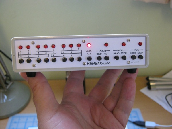
Additional photos of my build (2011) are here.
Original links here.
See kenbakuino.txt for detailed information about the sketch. It attempts to accurately emulate the original, but with some extensions: read from an RTC, generate random numbers, load built-in programs, etc.
Note if you download the zip from GitHub, after unzipping you will need to rename the "Kenbakuino-master" folder to just "Kenbakuino" since the IDE requires the folder to match the ino filename.
You can now buy a kit which uses the sketch and more closely matches the look of the original.
Changes since the original:
Dec '18 Extension #8: Send/Receive Memory over Serial. See serial.txt
May '19
- Extension #9: Auto-Run Program/Reset Configuration
- Constants to configure RTC
Jun '19 SYSX extensions to copy RAM to/from EEPROM. See memcopy.txt
Feb '20 By request, a couple of 24-hour mode versions of the BCD clock (STOP+Bit3). See 24hourBCDclocks.txt
Apr '21 Corrected CLR+STOR typo and SysInfo bug re delay set to 0ms.
May '21 Fixed right-shift sign extension and issues with multi-bit roll instructions.
NOTE: right-shift now preserves the "sign" as per original KENBAK-1. 0377 shifted right 1 is 0377!
Sep '22 Fixed program counter increment to happen after instruction executed.
NOTE: .lbl LDA 003 now sets A to lbl rather than lbl+2
Schematic (taken from PINS.H)
#ifndef pins_h
#define pins_h

// Pin assignments
// DS1307 - RTC (wire library)
#define PIN_RTC_SDA	A4
#define PIN_RTC_SCL	A5

// 74HC595 - LED driver
#define PIN_LEDS_DS	8
#define PIN_LEDS_ST	9
#define PIN_LEDS_SH	10

// 74HC165 - Switch driver
#define PIN_BTN_Q7	A0
#define PIN_BTN_CP	13
#define PIN_BTN_PL	12

// LEDS - direct connection
#define PIN_LED_INP	A1
#define PIN_LED_ADDR	A2
#define	PIN_LED_MEM	A3
#define PIN_LED_RUN_PWM	11

/*********************************************************
This is a *SCHEMATIC*
Pins not listed are unused/floating.
Component list:
  ATMega328, RTC module (DS1307), 74HC595, 74HC165 (x2),
  LED (x12), Push-button normally open (x15),
  Resistor 220 Ohm (x12), Resistor 10k Ohm (x15),
  16MHz crystal.
                 "KENBAK-uino" - Mark Wilson, 2011
                 +-----------+
                 |    328    |
  <USB>--[+5V]---+Vcc   PWM11+-------<LED11 "RUN">
  <USB>--[+5V]---+AVcc     A3+-------<LED10 "MEM">
  <USB>--[GND]---+Gnd(22)  A2+-------<LED9  "ADDR">
  <USB>--[GND]---+Gnd(8)   A1+-------<LED8  "INP">
  <USB>---[TX]---+TX         |
  <USB>---[RX]---+RX         |        +-----------+
                 |           |        |    595    |
      [XTAL1]----+XT1      10+--------+SH(11)   Q0+----<LED0 "Bit0">
      [XTAL2]----+XT2       9+--------+ST(12)   Q1+----<LED1 "Bit1">
                 |          8+--------+DS(14)   Q2+----<LED2 "Bit2">
                 |           |  [+5V]-+Vcc(16)  Q3+----<LED3 "Bit3">
                 |           |  [GND]-+Gnd(8)   Q4+----<LED4 "Bit4">
                 |           |  [+5V]-+MR(10)   Q5+----<LED5 "Bit5">
                 |           |  [GND]-+OE(13)   Q6+----<LED6 "Bit6">
                 |           |        |         Q7+----<LED7 "Bit7">
                 |           |        +-----------+
+------+         |           |
| RTC  |         |           |             +-----------+
|   SDA+---------+A4         |             |   165-1   |    **Note the order!**
|   SCL+---------+A5       A0+-------------+Q7(9)    D0+----<SW0 "Bit0">
|   Vcc+-[+5V]   |         13+-----+-------+CP(2)    D1+----<SW1 "Bit1">
|   Gnd+-[GND]   |         12+--+  |       |         D2+----<SW2 "Bit6">
+------+         +-----------+  +--|-------+PL(1)    D3+----<SW3 "Bit7">
                                |  | [GND]-+Gnd(8)   D4+----<SW4 "Bit4">
                                |  | [GND]-+CE(15)   D5+----<SW5 "Bit5">
                                |  | [+5V]-+Vcc(16)  D6+----<SW6 "Bit2">
                                |  |    +--+DS(10)   D7+----<SW7 "Bit3">
                                |  |    |  +-----------+
                                |  |    |
                                |  |    |
                                |  |    |  +-----------+
                                |  |    |  |   165-2   |    **Note the order!**
                                |  |    +--+Q7(9)    D0+----<SW8  "STOP">
                                |  +-------+CP(2)    D1+----<SW9  "STRT">
                                |          |         D2+----[GND] (SW15 is unused)
                                +----------+PL(1)    D3+----<SW10 "CLR">
                                     [GND]-+Gnd(8)   D4+----<SW11 "DISP">
                                     [GND]-+CE(15)   D5+----<SW12 "SET">
                                     [+5V]-+Vcc(16)  D6+----<SW13 "READ">
                                           |         D7+----<SW14 "STOR">
                                           +-----------+


where:
                   _  (Push-button, Normally Open)
                  + +
--<SWx> is   --+--+ +----[+5V]
               |
               +-[10kR]--[GND]

--<LEDx> is  --[220R]--[LED]--[GND]

**Note the order!**
This reflects the order I wired my switches to '165 pins.
You are free to change this to match the physical arrangement of the buttons,
BUT you will need to also change Buttons::m_pMap[] to match.

*********************************************************/
#endif