VERDICT Modeling Style Guide and User Manual V1 to support VERDICT VM 19.1 Tool Assessment 3
Contract # N6600118C4006
General Electric Research
December 11, 2019
Prepared by
Michael Durling, GE Research Heber Herencia-zapana, GE Research John Interrante, GE Research Baoluo (Paul) Meng, GE Research Abha Moitra, GE Research Kit Siu, GE Research
Daniel Prince, GE Aviation Systems
Cesare Tinelli, University of Iowa Omar Chowdhury, University of Iowa Daniel Larraz, University of Iowa Moosa Yahyazadeh, University of Iowa Fareed Arif, University of Iowa

This Wiki provides a technical description of the Verification Evidence and Resilient Design in Anticipation of Cybersecurity Threats (VERDICT) project which is part of the DARPA Cyber Assured Systems Engineering (CASE) program. The VERDICT team is composed of researchers and engineers from General Electric Research (GRC), General Electric Aviation Systems (GEAS), and the University of Iowa (UI). The team is creating the VERDICT tool to generate Fault and Attack-Defense trees with quantified reliability and likelihood of successful attack metrics, prove behavioral models meet formal cyber properties, identify the need for and suggest placement of run time monitors, and generate cyber test cases. This Wiki is intended to help end users of the tool understand how to create models and run the tool.
The Overall DARPA CASE Toolchain shown below is designed to enable System Engineers to analyze security along with other desired properties (e.g., safety, performance, cost, weight) at design time.
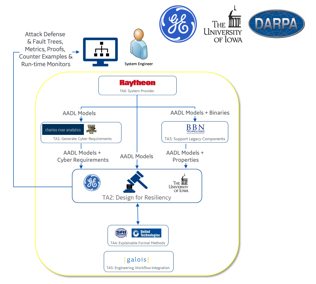
The program has seven Technical Areas (TA). TA 6 are the System Providers. They provide the systems to analyze including requirements, models, and code. TA 5 are the System Integrators. They facilitate integration of all the tools into a tool-chain. TA 4 is focused on Explainable Formal Methods. They are developing technology and tools that enables system engineers to benefit from formal methods technology without being formal methods experts. TA 3 supports Legacy Components such as binary and source code. TA 3 is working on tools that will extract models and properties from legacy code, so that it may be understood more clearly and reused. TA 2 is Design for Resiliency. The TA 2 performers are developing design tools to model, analyze and verify improvements in cyber-resiliency properties. The TA 1 performers are generating cyber-resiliency properties from the content provided to them by the TA 6 system providers.
The GE team is working on TA 2, Design for Resiliency. The GE VERDICT tool has two major functions. The first is the Model Based Architecture Synthesis (MBAS). The MBAS tool, takes in architecture models, mission, safety and cyber-resiliency requirements, then generates fault and attack-defense trees with resiliency metrics. The MBAS tool uses the fault and attack-defense tree information along with cybersecurity requirements and constraints as inputs to a synthesis function that in Phase 2 of the program will generate an architecture that meets predefined resiliency design constraints. The MBAS tool is built as an extension to a Fault Tree modeling and synthesis tool named SOTERIA that was developed previously for NASA. The MBAS tool enables the system engineer to model components, then synthesize architectures that meet both safety (based on fault tree analysis) and security (based on attack-defense tree analysis) design goals.
The second major function in the GE TA 2 Design for Resiliency project is the Cyber-Resiliency Verifier (CRV). The CRV takes in formal cyber-resiliency properties/requirements, architecture, and behavioral models - performs a formal analysis using an improved version of the Kind2 model checker developed at the University of Iowa, then returns design proof evidence, localized design errors, suggested run time monitors, and test cases.
The VERDICT 19.1 release includes the following new capabilities:
- Support for additional Component, Connector, Cyber Attack and Cyber Defense Properties
- Support for additional CAPEC threats and NIST-800-53 mitigations
- Support for hierarchical AADL models
The VERDICT 20.0 release planned for the PI Meeting in February 2020 intends to include the following new capabilities:
- Support for additional AADL language elements
- Update on integration of translator with the UTRC TA 4 team
At the time of the 2019 Tool Assessment #3 VERDICT 19.1 Release, the VERDICT tool supported a subset of the AADL language which is shown in the following list.
- system
- in data port
- out data port
- subcomponents
The VERDICT tool is implemented as a plug-in to the OSATE (Open Source AADL Tool Environment). The Tool Assessment #3 version of VERDICT is delivered with OSATE 2.6.0. This document provides an introduction to creating an AADL model for analysis with VERDICT.
To create a model for a system to be analyzed by VERDICT one must first create an AADL model in OSATE that captures the system's architecture. This model can be later enriched with VERDICT specific information.
Part of this information is added as VERDICT-specific AADL properties as described below. The rest, specifically, behavioral information, is entered as a formal specification in the AGREE language for each computational component of the system. More details on how to model a system's architecture in AADL and add behavioral specifications can be found in a tutorial available as Appendix A.
After your AADL model is created, you may add properties to it that will be used by the VERDICT tool during the analysis. There are five types of VERDICT Properties: 1) Component, 2) Connection and Port, 3) Cyber Attack, 4) Cyber Defense and 5) Design Assurance Level (DAL). The DAL properties are always used in combination with Cyber Defense properties. The VERDICT Properties are declared in the VERDICT_Properties.aadl file and then set for specific ports, connections and components in the "system implementation" section of the model. This section of the document provides more information on the various property types and how to use them.
TA 1 and 2 teams collaborated to develop the following table of Cyber Attack Properties. The teams will use these properties in 2020 versions of the tool chain to communicate cyber requirements from TA 1 to TA 2. For example, the first Cyber Attack Property in the table is Configuration Attack. TA 1 will assign the Configuration Attack property to the appropriate components and connections in the AADL model. If TA 1 assigns the Configuration Attack property to the Mission Management application in the AADL model, TA 2 would interpret that as "The Mission Management application shall be resilient to Configuration Attack".

Port and Connection properties are declared in the VERDICT_Properties.aadl file shown in the following figure. All AADL models that use VERDICT can use the same VERDICT_Properties.aadl file. System and Design Engineers use the properties in the implementation section of the AADL model to describe important attributes such as whether or not the connection is encrypted or authenticated.

Component properties are declared in the VERDICT_Properties.aadl file shown in the following figure. System and Design Engineers use the properties in the implementation section of the AADL model to describe important attributes such as whether or not the component is inside the trust boundary.

Cyber Defense and Design Assurance Level (DAL) properties are declared in the VERDICT_Properties.aadl file shown in the following figure. System and Design Engineers use the properties in the implementation section of the AADL model to describe important defense attributes and level of design assurance such as whether or not the connection or component has secure boot or encrypted storage.

The following figure shows VERDICT Component,Cyber Defense and DAL properties being set in the "Radio" system subcomponent in the system implementation section of the model. The Port, Connection, Component, Cyber Defense and DAL Properties will become part of design practice and included as common attributes for reused components. We intend to develop a library of common component AADL models that include VERDICT properties. The System and Design Engineers will review and perhaps update VERDICT properties during design, then perform VERDICT analysis and, based on the feedback, recommend additional safety and\or security mitigation.

Mission, Cyber & Safety Requirements, Cyber & Safety Relations, and Error Events are written in the AADL model using the VERDICT annex. Cyber, Safety and Mission Requirements may only be declared in a VERDICT annex within the top-level system type. Cyber Requirements can be aggregated and associated to a particular Mission Requirement. Cyber & Safety Relations may only be declared within a subcomponent system type, and they describe the vulnerability flow between the inputs and outputs of an individual component within the system. The following figure shows an AADL system model of a Camera. The Camera has one input port labeled camera_in and 2 output ports labeled camera_out and health_status. The VERDICT annex is used to define Cyber & Safety Relations for the camera out port, and Error Events for loss of availability and undetected erroneous data of the Camera.

The following figure shows the template for defining Mission Requirements in the VERDICT annex.

The following figure shows the template for defining Cyber Relations in the VERDICT annex. Cyber Relations are used to map component vulnerability of inputs to outputs. For example, the figure below shows that the Availability of out1 is impacted by the the Availability of in1 or in2.

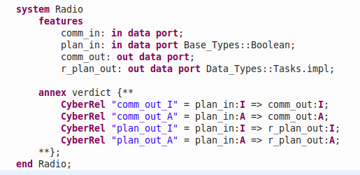
VERDICT requires the user to declare the Cyber Relations for each of the components in the AADL model. Cyber Relations represent the relationship of the input and output signals of a component. Cyber Relations are defined in the declaration section of the AADL model using the verdict annex. The figure below shows the the Cyber Relations for a Radio component. The comm_out integrity is impacted by the plan_in integrity, etc.
The following figure shows the template for defining Cyber Requirements in the VERDICT annex. Cyber Requirements must only be declared at the top most system level of the AADL project. It's a good practice to enter a message of the form "The <Confidentiality,Integrity,Availability> of the subject variable shall be <None, Minor, Major, Hazardous or Catastrophic> in the "description" field. For example - The Integrity of the estimated position signal input to the Navigator shall be Hazardous.

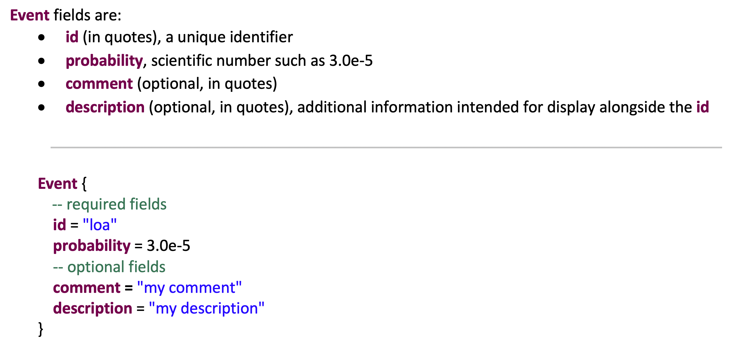
The following figure shows the template for defining Error Events in the VERDICT annex. Error events are defined in the declaration section of the AADL model using the VERDICT annex.
The following figure shows the template for defining Safety Relations in the VERDICT annex. Safety Relations are defined in the declaration section of the AADL model using the VERDICT annex.

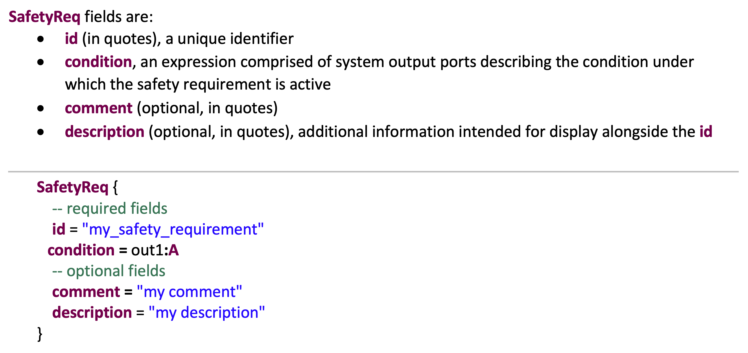
The following figure shows the template for defining Safety Requirements in the VERDICT annex. Safety Requirements must only be declared at the top most system level of the AADL project.
The following figure shows MBAS user feedback in the VERDICT tool. After the VERDICT MBAS tool is executed, user feedback is provided in the MBAS Result console tab. When the Acceptable Likelihood is not satisfied, the user can right click on the red failure icon to view the Failure Paths. This tab shows the Likelihood of successful attack for each of the attacked components, along with the CAPEC Attack Type and Suggested NIST 800-53 Defense. The System and Design Engineers using the VERDICT tool will use this information to help them understand where this system is vulnerable and to suggest options for improving resilience.

2.4.1 CAPEC Threats
The following figure shows a table listing all of the CAPEC threats supported by the 19.1 version of VERDICT. For more information on CAPEC, follow the link in the section title to the Mitre web site.

The following figure shows the mapping of CAPEC threats to NIST 800-53 mitigation controls and Cyber Defense Properties. The table is very useful when analyzing the MBAS feedback in the Failure Path tab.

2.4.2 Recommended Cyber Defense Mitigations (NIST 800 - 53)
The following table shows a list of NIST Defenses supported by the 19.1 version of VERDICT. For more information on NIST 800-53 Control defenses follow the link in the section title.

The following figure shows an example portion of an Attack Defense Tree graphic. These graphics are very broad and more appropriately viewed on a large scale display or poster plot. The Attack-Defense Tree svg files are located in the following directory - /home/ubuntu/VERDICT-0.6.0/extern/STEM/Output/Soteria_Output/

The following figure shows an example of the initial output from the fault tree analysis. Eventually, this output will be formatted to match the cyber feedback. The figure shows the Cutset probability of failure for Safety Requirement 2.

The following figure shows an example portion of a Fault Tree graphic. These graphics are very broad and more appropriately viewed on a large scale display or poster plot. The Fault Tree svg files are located in the following directory - /home/ubuntu/VERDICT-0.6.0/extern/STEM/Output/Soteria_Output/

The following figure shows Cyber Defense and Design Assurance Level properties being applied to the Navigation AADL model component, and the MBAS Result tab which shows that the model succeeded in terms of satisfying the Acceptable Likelihood of Successful Attack.

After the architecture has been revised to be secure, we then consider cyber-resiliency properties of the system design. To achieve this, the CRV component of VERDICT considers the system architecture (defined using AADL) together with a component-level specification of the system behavior formulated the AGREE language.
Capturing the component-level behavior allows CRV to take advantage of automated formal reasoning techniques such as model checking to analyze the satisfaction of formal cyber-resiliency properties while considering an adversarial environment.
The design philosophy of CRV is to decouple the modeling of the system's functionality from the possible security attacks it must withstand when deployed. The user is responsible for providing a system design model, a set of cyber-resiliency behavioral properties to analyze, and values for applicable VERDICT Properties. Then, the user only has to choose one or more appropriate threat models from a predefined list of such models under which to carry out the necessary formal resiliency analysis.
Unlike other approaches that rely on adversarial models capturing only known cyber-threats, CRV groups possible attacks based on their effects on the system and collectively reasons about them considering abstract threat effect models.
The class of cyber-resiliency properties currently supported by CRV consists of system integrity properties that can be formalized as temporal safety guarantees using the AGREE language. Considering integrity properties for a system under design is relevant as their violation can cause the system to take unintended actions which may jeopardize system safety or security.
The following figure shows an example of cyber-resiliency property written in AGREE for a Delivery Drone system:

Like MBAS, CRV also takes into account non-functional properties of the system for its analysis. The following figure shows the list of VERDICT Properties that are currently supported for the behavioral analysis:

The behavioral analysis depends on a set of configurable options. They can be accessed from the Cyber Resiliency Verifier (CRV) menu in OSATE:

The next subsections provides more information on these options.
The user can select zero or more threat (effect) models from the menu:

If no threat model is selected, CRV will check the satisfaction of the cyber-resiliency properties for the benign case, that is, without considering any adversarial model. This setting is useful as a sanity check to be sure the system design satisfies the properties in a benign scenario, when no attacks are present. It should be the first check to be performed, before analyzing the model under any adversarial environment. When one or more threat models are selected, CRV will check whether the system satisfies the cyber-resiliency properties when considering the possible effects of the selected threat models.
CRV implements a blame assignment technique to generate an explanation of cyber-resiliency property violations which details which components and links vulnerable to attack.

When the blame assignment analysis is enabled, CRV will try to identify a minimal number of responsible components or links to assist the System Designer in pinpointing the vulnerable parts of the system.
A component-level analysis will minimize the number of compromised components that must be compromised to carry out an successful attack. The analysis is done once CRV finds an execution trace that leads to a property violation. In contrast, a link-level analysis will minimize the number of compromised connections in the system.
The following figure shows CRV user feedback in the VERDICT tool. After the CRV is executed, this feedback is provided in the CRV Result console tab.

The tab shows the verification result for each system-level cyber-resiliency property, along with explanatory information if a property violation has been detected (red failure icon) and blame assignment was enabled. In the last case, the identified attack type is reported together with a minimal set of compromised ports involved in the attack. The user can right click on the red failure icon and select View Counter-example to view an execution trace that leads the system to a state where the property in question is violated, as shown in the following figure:

For each component port, the trace shows the list of values at each step of the execution.
To illustrate VERDICT, we created an architectural and behavioral AADL model of the delivery drone system. The package delivery operation consists of a van with packages to be delivered and one or more delivery drones. After the van arrives at a location that is close to multiple delivery sites, the delivery drones are initialized with their current position, delivery location, and the package to be delivered is loaded up. After a delivery drone is launched, it uses the inputs from the GPS and IMU to navigate to the delivery location. When the drone reaches the delivery location, it uses its Camera to capture an image of the receiving site to confirm that it is free of obstacles and it is safe for the package to be dropped off. For a high-value package, the Delivery Planner will use the Radio to get confirmation from the operator in the van. If there are no obstacles on the receiving site and confirmation (if needed) is received from the operator, then the Delivery Planner will activate the Delivery Item Mechanism to drop off the package.

The following figure shows the AADL diagram of the Delivery Drone model. At this point all of the components are AADL systems with inports and outports. The GNC component is an example of a hierarchical model. It contains the GPS and IMU components.

The following figure shows VERDICT annex being used to define the Delivery Drone System Cyber and Safety Requirements and then their assignment to the Mission Requirement.

The following figure shows the Radio component in the DeliveryDrone model. It shows the in ports and out ports, Cyber Relations, Error Events and Safety Relations. The complete model is available here.

Now we show an example with commented out Cyber Defenses and DAL's, then run the VERDICT MBAS analysis. The results will highlight the vulnerabilities in the model, show the calculated Likelihood of Successful Attack, the relevant CAPEC threats, and suggested NIST 800-53 defenses.
The following figure shows the Radio component from the Impl (implementation) section of the model. It is important to note that, based on the VERDICT Component Property definitions, the Radio is inside the trusted boundary, but is receiving both data and control from untrusted sources.

The following diagram shows the DeliveryDrone model selected on the left pane and the Run Model Based Architecture Analysis being selected from the Verdict - Model Based Architecture Synthesis tab on the main Pull Down pane. This initiates the translation of the AADL model to an Intermediate Modeling Language (IML) and then to the VERDICT design model and finally the analysis. The user can observe the steps of the progression in the Console pane. The process can take a couple of minutes.

The results of the analysis highlight the vulnerabilities in the Radio. You can also see that defenses have been applied to both the Actuation and Camera components. The figure shows that the Radio is vulnerable to a long list of CAPEC threats including 131, 25, 26, 607, 125, ..., and recommends NIST 800-53 defenses SC-6, SA 11-1, ... . At this point the System or Design Engineer using the tool would review the CAPEC (Vulnerability), NIST 800-53 (Defense Controls) and VERDICT Properties table to select the appropriate action and design assurance level. This tool allows the user to select defense properties to make the system more resilient in the architectural model, but it is up to the designers at the next level to make sure the properties are satisfied in the implementation. Mapping the properties to an assurance case is one approach to managing the information to ensure traceability and follow through.

The following figure shows all of the VERDICT Cyber Defense Properties and DAL's set that should resolve all of the feedback. The user may want to experiment with commenting out subsets of the property and DAL set to understand the relationship between CAPEC's, VERDICT Properties and NIST 800-53 Defense Controls.

The following figure shows the MBAS Results after the resiliency design improvements were made to the architectural model.

We show now how to perform behavioral analysis on our running example model, first in the benign case and then under the assumption of one or more possible attacks.
To perform the behavioral analysis on our model, we need to:
-
extend the architectural model with the fair amount of behavioral information for the components, in the form of AGREE assume-guarantee contracts; and,
-
specify system-level properties of interest to be verified by VERDICT given the expressed behaviors.
For each of these two main steps, VERDICT can carry out a thorough behavioral analysis on the given model under the user-selected threat models. in particular, VERDICT's behavioral analysis will answer the following questions:
-
Does this behavioral model satisfy the specified properties under the target threat models?
-
For any property falsified, which threat was it vulnerable to? And which component(s) could be responsible for that vulnerability?
In what follows, we will explain the steps needed for performing behavioral analysis.
In the first step, we need to add behavior for the components in the architectural model of our Delivery Drone system. As you have seen in Section 4.1, an architectural model consists of high-level definition of each component including its interface (i.e., in ports and out ports), cyber relations, error events, and safety relations. Now we specify the intended functionality of that component. Using AGREE contract to specify that the functionality allows us to choose a level of abstraction in the specification that is enough to prove the system-level cyber-resilience property (as opposed to provide a complete and detailed specification). This functional behavior, for each component, simply expresses temporal constraints between the values of out ports and the value or in ports. Sometimes these constraints may need to be expressed also in terms of the internal state of a component. In that case, relevant information on the internal states may be provided in virtual output ports that we refer to as probes.
Now let's revisit the Radio component in our Delivery Drone model. This component has the following in port–out port interface:
-
comm_in: in port representing radio response communication -
radio_in: in port representing a command issued for radio communication to base station -
comm_out: out port representing radio request communication -
radio_out: out port representing radio response data received from the communication -
health_status: out port representing the health status of the radio component
Specifying the relation between out ports and in ports (and/or the internal states) depends on the level of abstraction we want to have for this component which eventually hinges on the properties we want to verify. However, the rule of thumb is to stay at the highest level of abstraction first and then try to verify the properties. If we need to specify more about this component to prove the desired system-level properties we can refine its specification later.
Now, for radio component we know at least the following:
- Two main pieces of information in the radio communication are important to us: (i) communication data is available (ii) data shows the delivery target is confirmed.
- The radio component receives data from the remote communication channel (i.e.,
comm_in) and presents the response data at itsradio_outout port if a command was issued for radio communication - If no command for radio communication (i.e.,
radio_in) is issued, there is no available radio data.
This is a minimal level of information about about the expected behavior of the radio component. To formalize (1), we define a record using the following syntax.
data RadioResponse
end RadioResponse;

data implementation RadioResponse.impl
    subcomponents
        data_available: data Base_Types::Boolean;
  	target_confirmed: data Base_Types::Boolean;
end RadioResponse.impl;
To specify point (2) above, we add a guarantee stating that radio_out is the same as comm_in when radio_in is true:
guarantee "Radio receives data from remote communication channel
           if there is a request":
  radio_in => (radio_out.data_available = comm_in.data_available and
     	 	   comm_in.target_confirmed = radio_out.target_confirmed);
Similarly, for point (3) we add the following guarantee:
guarantee "Without a request, no radio data is available":
    not radio_in => not radio_out.data_available;
The behavioral requirements above are included inside the AGREE annex as follows:
annex agree {**
    guarantee "Radio receives data from remote communication channel
               if there is a request":
    radio_in => (radio_out.data_available = comm_in.data_available and
     	 	     comm_in.target_confirmed = radio_out.target_confirmed);
    guarantee "Without a request, no radio data is available":
	not radio_in => not radio_out.data_available;
**};
As can be seen, so far we have only added constraints about the radio_out out port. Any value that satisfies those constraints will be considered valid during the analysis performed by CVR. This also means that since we have not added any constraints about comm_out and health_status, CRV will assume that they can take any value allowed by their type.
There are situations when one needs to add more detail to the specification in order to capture the behavior of a component more precisely. This can be seen in the specification of DeliveryPlanner component here. This the AGREE specification of that component relies on an abstract representation of the component internal states (using mode notion) to specify its functionality.
The next step is to review the list of safety functional requirements for the system that may affect its integrity, and formalize them as formal cyber-resiliency properties in the AGREE language.
For instance, let's consider the following cyber-requirement for DeliveryDroneSystem that talks about the drone operation and the radio communication: A command to release a valuable package is issued only if drone has received confirmation from base.
To formalize this cyber-requirement we have to identify first the components and ports of the system that are relevant for the description of the property. In our example, the Radio is the component that receives the confirmation through the input port comm1, and the DeliveryPlanner is the component that issues the command to release a package by setting the output port delivery_cmd to RELEASE_PACKAGE_CMD. Moreover, to know whether a package is valuable or not, we need to check the item value of the most recent order, which is transmitted through the input port bus1.
Notioce that some event conditions in our property only depends on the value of a port in the current step, for example, when a command to release a package is issued. However, other conditions depends on past values of one or more signals, like the item value of the most recent order, or the fact that a confirmation from base has been received. In the later case we will use temporal operators, like pre or HasHappened, to express conditions about past values. Furthermore, we will introduce local variables to simplify the definition of conditions and values.
For instance, we can declare a local variable called most_recent_order that will act as a register. It will store the most recent value of the field order of the input port bus1 when the drone is in the initialization mode, and it will keep the last registered value otherwise. If no such previous value exists, it will use an arbitrary order value.
eq arbitrary_value: Data_Types::DeliveryOrder.impl = ...

eq most_recent_order: Data_Types::DeliveryOrder.impl =
  if init_mode then
    bus1.order
  else
    arbitrary_value -> pre(most_recent_order);
There is one problem with the previous definition. The variable init_mode is a local variable of DeliveryPlanner's contract that is not accessible from the DeliveryDroneSystem interface. For these cases, the interface of DeliveryPlanner and DeliveryDroneSystem can be extended with a probe signal which is not part of the actual architecture of the system, but it will be used only for specification and verification purposes. In order to identity the new port as a probe, the user can set the VERDICT property probe to true for the new port:
probe_init_mode: out data port Base_Types::Boolean
{ VERDICT_Properties::probe => true; };
Here is again the definition of most_recent_order using the new probe port probe_init_mode. For simplicity's shake, the revised definition uses the initial value of bus1.order as the arbitrary value for most_recent_order in case of no initialization:
eq most_recent_order: Data_Types::DeliveryOrder.impl =
  if probe_init_mode then
    bus1.order
  else
    bus1.order -> pre(most_recent_order);
Once most_recent_order has been defined, we can express easily that a package is valuable if the item value of the most recent order is greater or equal to a threshold value:
eq valuable_package: bool =
  most_recent_order.item_value >=
  Agree_Constants.ITEM_VALUE_THRESHOLD;
We said above that a command to release a package is issued if delivery_cmd is set to RELEASE_PACKAGE_CMD. We can capture this condition with the following local definition:
eq release_cmd: bool =
  probe_delivery_cmd = Agree_Constants.RELEASE_PACKAGE_CMD;
where probe_delivery_cmd is a probe signal for delivery_cmd.
The last definition we need before we can express our cyber-resiliency property is for the confirmation event. We would say a confirmation from base has been received if at any point in the past a confirmation was requested by setting radio_cmd to true, and an acknowledge was received through input port comm1. The first condition can be defined as follows:
eq confirmation_requested: bool =
  Agree_Nodes.HasHappened(radio_cmd);
where the unary temporal operator HasHappened(X) is true at any point if and only if X has been true from the beginning until that point.
The second condition is true when radio data is available and the confirmation is positive:
eq acknowledge_received: bool =
  comm1.data_available and
  comm1.target_confirmed;
Using the definition for the first and second condition, now we can define target_confirmed as follows:
eq target_confirmed: bool =
 Agree_Nodes.HasHappened(
   confirmation_requested and
   acknowledge_received
 );
Finally, we express the definition of the cyber-resiliency property as a guarantee for DeliveryDroneSystem using the previous defined auxiliary variables:
guarantee "P4: a command to release a valuable package is issued only
           if drone has received confirmation from base":
  release_cmd and valuable_package => target_confirmed;
Once we have specified formally the properties of interest, the first thing we have to check is that our system design model satisfies all the properties in a benign scenario, that is, without considering the effects of any threat model. In order to do that, open the CRV Settings window:
Make sure no Threat Model is selected, and save the settings:
Select DeliveryDrone model on the left pane, and select Run Cyber Resilience Verifier from the Verdict - Cyber Resilience Verifies (CRV) tab on the Verdict menu:

This initiates the translation of the AADL model to an Intermediate Modeling Language (IML) and then to the VERDICT design model and finally the analysis. The user can observe the steps of the progression in the Console pane. The process can take from several minutes.
The result of the analysis confirms that all cyber-resiliency properties, including property P4 described in the previous section, are satisfied in the benign scenario:

If this had not been the case, that is, one or more property violations would have been detected, it would be time to review the system design model because that might be indicative of a faulty behavioral specification.
After checking all cyber-resiliency properties are satisfied in the benign case (see previous section), it is time for analyzing the behavioral model under an adversarial environment. For that, we have to repeat the steps described in the previous section except that now we will select two threat models, Network Injection and Remote Code Injection, that we suspect could lead to the identification of an attack that violates property P4 defined in Section 4.3.2. We will also make sure the Blame Assignment option is selected:

The following figure shows the result of the analysis after running CRV using the new setting:
All properties except P4 are satisfied under the effects of the two selected threat models. Moreover, CRV is able to identify a Network Injection attack by compromising only the data going through port comm1. The user can right click on the red failure icon and select View Counter-example to view an execution trace that leads the system to a state where property P4 is violated as it is shown in the following figure:
Once a vulnerable component or connection is identified, the user can consider multiple possibilities to address the root cause of the attack. Let's assume the user decide in this case to introduce resiliency measures such as cryptographic authentication and encryption for the compromised connection. The user can inform the tool about these measures by changing the corresponding VERDICT property values for the connection:

A new analysis of the system confirm the applied fix is enough to rule out new Network Injection attacks:
The VERDICT team provides a fully functioning version of the tool in a Virtual Machine (VM) format for ease of installation and setup for end users. For team members the VM (VERDICT.ova) file is available on the team share site. The file is large (~7.5 GB). We run the file in a Virtual Box application downloaded from https://www.virtualbox.org/. On a Windows system, the user should download and install the Virtual Box, then import the .ova appliance. Once the VERDICT.ova file is in the Virtual Box, the user simply selects the start arrow to run the VM.
The following figure shows the VERDICT.ova file (appliance) loaded in the Virtual Box application.

The following figure shows the desktop of the VM running in Virtual Box. The OSATE icon is on the lower left side of the desktop. Double click the OSATE icon to open the AADL environment and start working with VERDICT.

- Move the mouse to the folder icon in your VirtualBox window’s tray.

- Click the right mouse button on the folder icon, then click on the Shared Folder Settings when it pops up.

- Click on the green folder+ icon to add a new shared folder.

- Enter the new folder’s location in the Folder Path. Click the OK button.

- Click the OK button to save the new Shared Folder setting.

- Now the folder icon in the VirtualBox window’s tray will have a blue color and if you mouse over it, it will pop up the name of the shared folder that is available to the VM.

- You still need to do one more step before the VM can use the shared folder. Open a terminal window and run the following command: sudo mount -t vboxsf VMShare /mnt.

- Now you can copy files between /mnt and /home/ubuntu as necessary. If you need to remove or change the shared folder later, run the following command: sudo umount /mnt.

The main capability improvements to VERDICT in the V19.1 release are:
- Support for safety modeling, cutset and fault tree generation
- Support for significantly more CAPEC threats and NIST 800-53 defenses
- Support for hierarchical modeling of sub-components in AADL
This document provided a summary of the capability currently implemented in the VERDICT tool and demonstrated it on a delivery drone use case. The tool worked well in terms of identifying vulnerabilities in the community accepted CAPEC attack patterns, and suggested NIST 800-53 defensive design modifications to improve system resiliency. In the next major sprint, the team plans to add support for additional AADL language elements.
This annex describes how to use AADL to model the architecture and behavior of a simple settable thermostat. The aim of this tutorial is to introduce through an example the main concepts of top-down component-based design in AADL, and to show the specific AADL modeling constructs supported by the VERDICT tool chain.
In the following section, we present a top-level specification for a simplified design of a domestic thermostat system. Then we decompose the thermostat system into subsystems, and show how to represent this hierarchy in AADL. After modeling the architecture, we show how to use the AGREE annex, an assume-guarantee-style dataflow specification language, to describe the behavior of the subcomponents. Finally, we will annotate the top-level system with some formal properties describing the expected behavior of the whole system.
 We want to model a thermostat controller for regulating the temperature in a room. The task of the controller is to make sure that the room temperature stays close to the reference temperature set by the user on the thermostat. The figure on the right shows the control panel for the thermostat. It has a switch with three positions (Cool, Off, and Heat), two buttons (Up and Down), and a display that shows at all times the reference temperature, the _set point_. The user can use the switch to place the system in one of the three possible settings, and the two buttons to increase or decrease the desired temperature. The controller can influence the temperature by turning on and off an air conditioning system and a furnace, and it can check the current temperature by reading the value provided by a temperature sensor. When the system is in the Cool setting and the current room temperature (as measured by the sensor) is higher than the set point, the controller sends an activation signal to the air conditioner until the measured temperature goes down to the set point or below. When the system in the Heat setting and the measured temperature is lower than the set point, the controller sends an activation signal to the furnace until that temperature goes up to the set point or above it. To prevent the thermostat from activating the air conditioner or the furnace continually as the room temperature oscillates around the set point, we define a _deadband_, an interval around the set point value, in which neither system will turn on.
The following figure shows the inputs and outputs of the thermostat controller according to the description above:
We want to model a thermostat controller for regulating the temperature in a room. The task of the controller is to make sure that the room temperature stays close to the reference temperature set by the user on the thermostat. The figure on the right shows the control panel for the thermostat. It has a switch with three positions (Cool, Off, and Heat), two buttons (Up and Down), and a display that shows at all times the reference temperature, the _set point_. The user can use the switch to place the system in one of the three possible settings, and the two buttons to increase or decrease the desired temperature. The controller can influence the temperature by turning on and off an air conditioning system and a furnace, and it can check the current temperature by reading the value provided by a temperature sensor. When the system is in the Cool setting and the current room temperature (as measured by the sensor) is higher than the set point, the controller sends an activation signal to the air conditioner until the measured temperature goes down to the set point or below. When the system in the Heat setting and the measured temperature is lower than the set point, the controller sends an activation signal to the furnace until that temperature goes up to the set point or above it. To prevent the thermostat from activating the air conditioner or the furnace continually as the room temperature oscillates around the set point, we define a _deadband_, an interval around the set point value, in which neither system will turn on.
The following figure shows the inputs and outputs of the thermostat controller according to the description above:

As a next step in the design, we can conceptually decompose the thermostat controller into two subsystems: component SetDesiredTemperature which keeps track of the reference temperature, and component ControlTemperature which controls the activation signals that turn the air conditioner and the furnace on and off. The interconnections among these subcomponents are shown in the following diagram:

This design can be captured in an AADL model as detailed in the next section.
The architecture of the system, consisting in its component subcomponents and their connections is defined using standard AADL constructs. AADL does not have a native sublanguage for specifying in a formal way the behavior of a component. This can be done, however, with an AADL annex specifically designed for this purpose by Rockwell-Collins: the AGREE annex.
To model an architectural design like this one in AADL one starts by defining each (sub)component and its interface. Each component is defined independently as a system. Here is a possible specification in AADL of ThermostatController, the top-level component in our example, that reflects the first diagram above:

And here is the specification for the ControlTemperature subcomponent:

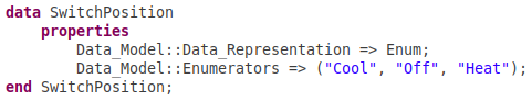
For each component we list the set of input and output ports that the component uses to communicate with its environment, and the type of data exchanged in each of its port. In addition to base types, such as Boolean, Float and so on, AADL allows one to use user-defined data types for ports. For instance, SwitchPosition is an user-defined enumeration type that models the three possible positions of the thermostat switch:
Once we have defined the interface of the components, we can describe their internal structure. Starting with the top-level component ThermostatController, we do that by defining a system implementation for the component:

The implementation construct allows us to specify the system's subcomponents as well as how they are connected together. In this case, the subcomponents are set_desired_temperature and control_temperature defined respectively as instances of ThermostatController and ControlTemperature. (In terms of object-oriented programming concepts, one can understand systems are classes and subcomponents as class instances).
Once the architectural design is in place, we can describe the behavior of each subcomponent. We do that by associating an assume-guarantee contract to each component. The contract specifies the component's input-output behavior as guarantees provided by the component whenever its environment satisfies certain given assumptions. Intuitively, assumptions describe the expectations the component has on the environment, while guarantees describe restrictions on its output. Assume-guarantee contracts in AGREE are in essence statements in a temporal logic rich enough to describe precisely a component's behavior from the point of view of an observer that, at all times, has access to all the input and output values until so far. Contracts provide a mechanism for capturing the information needed to specify and reason about component-level properties at a desired level of abstraction.
Technical note: The AGREE language is inspired by, and is very close to, the synchronous dataflow language Lustre. In AGREE, every system can be seen as taking as input one or more infinite streams of values (with all values in a stream having the same type), and producing one or more infinite streams as output. The overall system is assumed to run on a universal base clock that represents the smallest time span the system is able to distinguish. Note that the restriction to a synchronous model of computation is intentional, because of its simplicity, but does not cause a loss of generality since asynchronous systems can be faithfully simulated in it in a variety of ways. Our thermostat example can be modeled directly as a synchronous system. The behavior of this system can be formalized by specifying how, at each tick of the base clock, or step, the system's output relates to the current input and past values of the input and output ports as well as the current and past values of local variables (which can be understood as registers).
Let's start with the specification of component SetDesiredTemperature. Recall that this component receives two inputs, up_button and down_button, each of them indicating if the corresponding button is being pressed in the current step, and computes one output, the current value of setpoint. When the user presses the up button, the set point is increased by some fixed amount. We will use a global constant called DIFF to represent such amount. When the user presses the down button, the set point is decreased by the same amount. If neither button is pressed, the set point value doesn't change in that step. More precisely, the set point value changes as long as it stays within a reasonable temperature range, given by a minimum value and a maximum value, denoted respectively by the global constants MIN_TEMPERATURE and MAX_TEMPERATURE. The following AADL snippet shows the interface and AGREE contract specification for SetDesiredTemperature that captures the requirements above:

Each guarantee specifies the current value of setpoint in terms of the auxiliary variable prev_setpoint, which represents the value of setpoint in the previous step. The contract includes the definition of two more auxiliary variables, increment_condition and decrement_condition, that specify the condition under which the setpoint value is to be incremented or decremented.
Auxiliary variables are introduced by eq keyword and are given a name, a type and a definition. The definition of prev_setpoint is given by the combination of the infix initialization operator -> and the delay operator pre. The -> operator can be used to specify the initial value of a port or variable (with the left-hand argument) and later values (with the right-hand argument). An expression of the form e1 -> e2 evaluates to the value of expression e1 initially and to the value of e2 at all later steps of the system's computation. The pre operator is used to refer to the value of an expression in the previous step, if any. That is, at each step i other than the initial one pre(e) denotes the value that e had in step i-1, and is undefined at step 0, the initial step. This means that a pre application should always be guarded by an -> expression, as in the definition of prev_setpoint. That definition specifies that the initial value of prev_setpoint is that of the global constant INITIAL_TEMPERATURE; at each later step it is instead the previous value of setpoint.
Assumptions and guarantees are introduced respectively by the keyword assume and guarantee. They have an optional name, given as a string literal, and a definition. The latter is any expression of (AGREE) type bool which is a synonym of the AADL type Boolean. Expressions of type bool can be built out of ports of type Boolean; auxiliary variables of type bool; relational operators such as =, <, <=, >=, and so on; and various Boolean operators for negation (not), conjunction (and),disjunction (or), , implication (=>), and alternative (if _ then _ else).
Now we will model the behavior of the component ControlTemperature. This component receives as input the position of the switch, the current room temperature, and the current set point, and outputs (as Boolean values) activation signals for the external heating and cooling units. Its behavior can be naturally modeled by describing what the component should do depending on the specific situation, or mode, it is in. Abstractly, we can say that at any one time, the component is in one of three different modes which we represent by three Boolean variables: cool_mode, heat_mode, and off_mode. Each of them is supposed to be true exactly when the thermostat is in the corresponding mode. The cooling (resp., heating) activation signal should be true exactly when controller is in Cool (resp., Heat) mode. Let's consider first the definition of the Cool mode. The component should be in Cool mode in exactly two cases:
-
The current room temperature is outside the deadband region, and the switch is in the Cool position.
-
The current temperature was outside the deadband region in an earlier step, the switch has been in the Cool position since then, and the current temperature is still higher than the set point.
The definition of the Heat mode is analogous. Finally, the component should be in Off mode exactly when it is not in Cool or Heat mode. Intuitively this includes all times the input switch is in the off position but also the times when switched has been most recently moved to one of the other two positions but the current temperature is still within the deadband region. (Recall that we do not want heating or cooling to start until the current temperature is outside that region.)
All requirements are formalized by the following AGREE specification ControlTemperature.

By the definition of the binary operator enum in AGREE, the predicate enum(SwitchPosition, Cool) is true exactly at those times when the value of SwitchPosition is Cool. The values of the other applications of enum are defined analogously.
Note that since we decided to make the definition of the Cool and Heat modes coincide with the cases when the corresponding activation signals are supposed to be true, the definition of those signals becomes trivial and corresponds directly to the values of the Boolean variables cool_mode and heat_mode.
Once we have defined a contract for the subcomponents of the thermostat controller, we can proceed to specify some properties that the controller should satisfy. We will express these properties as a contract for the top-level component ThermostatController. Note that, in the spirit of compositional reasoning enabled by assume-guaranteed contracts, we do not need, and should not need, to know how the two subcomponents are implemented to be able to reason about whether the the top-level component satisfies its contract. In other words, the implementation of ThermostatController and the contracts of SetDesiredTemperature and ControlTemperature, are supposed to be enough to prove the properties of ThermostatController. If they are not, then one of the three contracts or the specification of ThermostatController's implementation needs to be revised. We illustrate this in some detail next, in particular, showing how the results of the analysis provided by VERDICT suggests which part of the behavioral model needs revising when one of the top-level properties is falsified.
We start with four basic properties over the activation signals:

Then we specify four properties over the set point:

Unfortunately, the last two properties don't hold with the current specification. To see why let's consider the last one. This property is violated every time the current value of setpoint is MIN_TEMPERATURE and the up and down input signals are simultaneously true. VERDICT can show this by providing a counterexample trace for the property. The same analysis will show that the increment condition defined in the SetDesiredTemperature contract is satisfied. It must be then the case that setpoint is increased by DIFF. But this violates the property when the down button is also pressed. We can argue about the other property in a similar way. Our first reaction to this should be to double-check the two properties and convince ourselves that we have formalized them correctly. Since this is the case here, we should then ask ourselves whether it is justified to assume that up_button and down_button are never true at the same time given that the problem identified by the analysis occurs when they are both true. If this assumption about the system's environment is justified, we can formalize it by adding the following clause to the specification:

Observe that the assumption talks explicitly about the values of the two inputs being mutually exclusive just in the current step. However, since the current step is arbitrary it effectively expresses a universal restriction on all steps. The same observation applies to guarantees as well.
Finally, we consider these other properties that involve the activation signals, the set point, and the current temperature:

The last two properties use the binary temporal operator Since which is defined so that Since(X,Y) which is true precisely when X has been true at some point, and Y has been continuously true afterwards. AGREE provides a number of temporal operators that facilitate the formalization of assumptions and guarantees. Thanks to the power of the specification language, however, none of them is primitive as it can be defined (basically as a macro) in terms of the operators we have already seen. For instance, here is the definition of Since:

Additional operators, temporal or not, can be defined by the user by providing node definitions like the one above.
The final AADL model for the Thermostat Controller is available here. You can comment out the assumption "Up/Down button signals are mutually exclusive" (by prepending it with --) to verify the failure of the two setpoint properties mentioned earlier.