Prometheus Version 2

| ITEMS | DESCRIPTION | QUANTITY |
|---|---|---|
| Raspberry Pi 3B | Runs all the logic and supplies 5V to the motor driver | x1 |
| L293D | Motor Driver that is will either allow the circuit to the vibrator, or stop it based on logic signals | x1 (I would bulk buy some extras in case you make a mistake) |
| SonicAlert SS12V Bed Shaker (Or some other vibration capable device) | Bed shaker, runs 12V @ 0.5A (peak 12V @ 1.0A) Center Pin Positive | x1 |
| Wires | Breadboard wires. Make sure they can withstand some amount of current (12V), if you don't have a Pi | |
| Prototype Solder Board | To connect (solder) the wires to the L293D | x1 |
| RPi Compatible Soundcard | Provides even better audio than USB Audio Interface used in v1 (Personally using the HiFiBerry Digi+ Pro and very satisfied with the result) | x1 |
| HQ Sound Cable | I am using an SPDIFF cable (a.k.a. optical) to get the best possible sound resolution between my Pi's sound card and my external sound system. | x1 |
| 12V @3A+ DC Power Supply | Up from 12V @1A because we are using a single power source to power everything (Pi + Soundcard, Nixie Display, Bed Vibrator, Racing Switch LED | x1 |
| Wall-Mount Barrel Plugs (5.5x2.1mm) | Since we want to mount the plugs into the clock's enclosure, you will need 2 wall-mounted ones (rather than breadboard ones) One for the 12V power in, and one to power the SSV12 Bed Vibrator | x2 |
| Arduino based Nixie Clock | You have some freedom here, but I personally chose GRA & AFCH NCS 314 which runs on Arduino (not included). An important note: The Pi is NOT directly controlling the cold cathode displays. The logic to run the clock is running on the Arduino itself. Instead of a master -> slave architecture, Prometheus is only sending the time + LED information via serial USB, and the Arduino logic board is controlling the analog switching required to run the nixie clock as well as self-adjusting its own internal clock based on that information | x1 |
| Spare USB Cable | To save on space, you are going to want to strip a USB cable (leaving the USB type A side intact and solder it directly to the USB port on the Arduino | x1 |
| 12V to 5V Step Converter | Since we want a single power supply to power everything (and Raspberry Pi will definitely burn out if you use 12V, we need to convert it to a stable 5V for the Pi + soundcard circuit) | 1x |
| 12V Power Toggle Switch | This adds a separate mechanism to enable or disable the circuits other than just unplugging the device. I am using a three toggle racing switch (made for cars) to independently control the circuits powering the nixie clock, the Raspberry Pi, and the bed vibrator separately. Although 3 might be overkill , you will want at least 2 for reasons I will explain later. | 2x-3x |
|
|
Unlike v1, Prometheus v2 uses a single 12V power supply to power all components. Although the end result is a cleaner build, the schematic's complexity increased slightly.
The main Prometheus program is run on the Raspberry Pi. The Raspberry Pi is responsible for hosting a small website which acts as the user interface for the alarms, getting accurate time from the web (which it will use to check if the user supplied alarm time matches the current time at the beginning of every minute as well as updating the nixie clock with the most accurate time via serial USB), sending the logical signals to the L293D motor driver chip (to enable or disable the 12V current to the bed vibrator) via GPIO pins, and outputting alarm sounds (to a external sound system).
Since the Pi needs a 5V power supply, we will use a 12V -> 5V converter to get the 5V power we need. Furthermore, instead of using the standard micro-USB port, we will power the Pi through the sound card's interface.
 Ignore the 3.3V part. The updated HifiBerry Digi+ Pro gets the 3.3V power from the 5V.
 Ignore the 3.3V part. The updated
 The L293D motor driver is a bi-directional motor driving chip which enables or disables a 12V current (or even reverses the direction of the current) based on 3 digital logical signals. We will be using this to power the bed vibrator. (For our purposes, think of it as a standard room light switch that is controlled digitally rather than through a physical flip of the switch.) Although it fits within the capabilities of the L293D, we definitely don't want to reverse the current for fear of damaging the Bed Vibrator.
Observe the following L293D schematic.
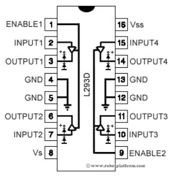
This means that we need the following connections to supply power to the chip (both the 12V circuit that the chip controls, and the 5V that controls the chip).
| L293D Pin | Description |
|---|---|
| 4 | Connects to the 5V GND |
| 5 | Connects to the 5V GND |
| 8 | Connects with the 12V+ power. |
| 9 | Connects to Pi 2 5V+ |
| 12 | 12V Ground |
| 13 | 12V Ground |
To power the bed vibrator, we want to wire the bed vibrator to the L293D circuit as follows:
| L293D Pin | Description |
|---|---|
| 3 | The cathode (+) for the Bed Vibrator |
| 6 | The anode (-) for the Bed Vibrator |
The logical signal to enable the 12V circuit is:
| L293D Pin | Digital Boolean |
|---|---|
| 1 | True |
| 2 | True |
| 7 | False |
Furthermore, the logical signal to disable the 12V circuit is:
| L293D Pin | Digital Boolean |
|---|---|
| 1 | False |
| 2 | True/False |
| 7 | True/False |
Programmatically, I am sending
Falseto all three connections, but as long as you disableEnable1, the circuit is stopped.
Therefore, in order to use Pi GPIO pin 17 as the Enable1, Pi GPIO pin 22 as Input1, and Pi GPIO pin 23 as Input2, connect the RPi GPIO pins to L293D pins as follows:
| L293D Pin | Description |
|---|---|
| 1 | Connects to the Pi GPIO Pin 17 |
| 2 | Connects to the Pi GPIO Pin 22 |
| 7 | Connects to Pi GPIO Pin 23 |
Note, I had to change pin 5 to 22 and pin 6 to 23 from my original prototype schematic since my RPi sound card uses both 5 and 6.
Since the Hifiberry Digi+ Pro mounts on top of the GPIO pins, we will need to access the pins via the Digi+ Pro's interface. However, the locations of the pins on the Digi+ Pro mirrors the location on the Raspberry Pi so this will not be that hard.

Please use the following picture as a reference to soldering the L293D board to a prototype board.

I found a medical grade step down converter which converts 12V to 5V. The converted 5V current is powering both the Raspberry Pi (via the soundcard's interface) and the L293D.

Although if you down the audiophile sound rabbit hole, they will tell you you need to get a $200 linear power supply (if you do not know what this means, don't worry about it), I found that my cheap power supply + conversion components were fine (I found no discernible audio degredation [albeit, I am no audiophile, nor sound engineer]).
NCS314 by GRA & Afch is a nixie clock shield that mounts on top of an Arduino Uno board. An Arduino mounted NCS314 functions as a standalone clock (even with its own alarm sounding mechanism using a micro-speaker system). They wrote a set of arduino sketches that fully control the cold cathode displays (while keeping track of time using a RTC module on board the shield). However, after I built the prototype, I noticed that the RTC1307 module they were using was highly inaccurate, with time drifting about 10 minutes or so every month. Although the Raspberry Pi lacks an RTC module entirely, it receives accurate time via the NTP protocol as long as it is connected to the internet. Hence, I decided to add a portion of the main Prometheus program to send the most updated time to the Arduino via serial USB every second.
In order to do this, we need to make sure the Raspberry Pi and the clock is connected by a USB connection. Although it entirely possible to just connect the USB type B connector on the Arduino, since my enclosure was too narrow to connect a full USB type B, I decided to solder the USB wires directly to the underside of the Arduino (I also soldered the 12V power wires directly underneath the barrel jack on the Arduino as well).

The USB is VERY difficult to solder as the 4 pins on the Arduino are so close to each other. This is problematic since you can only use a VERY small amount of solder make sure that the USB connectors don't short circuit. Because of the lack of solder, the connections between the wire and the connector kept on detaching. To prevent this from happening, I used a hot glue gun to solidify the joints on top of soldered areas.


The toggle switch adds a mechanism to power down the clock without having to resort to unplugging it. Although it is theoretically possible to survive with 1 toggle switch, I suggest having 2 (1 for the nixie clock, and 1 for the 5V step converter powering the Pi and the 5V on the L293D) because the clock runs tests during its initialization sequence which delays the actual start of the main loop for the clock (which will cause problems on the Pi side because the clock will not be visible as a serial USB device).
Toggle switches will generally have 3 wire connectors. One will be the power into the toggle switch, the second will will be the power cathode to the device you are trying to power, and the third is the ground.

You will ground device directly to the same ground as the toggle switch. When the switch is flipped on, the 12V-in and the device cathode will connect, enabling the circuit. Off will cut this connection off.
I personally am using a three switch racing toggle. I use the first toggle for the nixie clock, the second toggle for the 12V->5V step down converter, and the third toggle for the L293D VIn.
Those are all the components that Prometheus is built on.
Here are some pictures of my set-up to help you get started.


