Periodic SysTick Interrupts
SysTick can be used to create periodic interrupts. Periodic interrupts are useful for data acquisition systems, low-bandwidth devices where real-time response is not necessary, when we wish to perform I/O functions in the background, or when we cannot generate interrupts directly.
The example on this page illustrates how you can use a SysTick periodic interrupt to produce a square wave on PF2 (on for 1ms, and off for 1ms). A breakdown of the registers used in the example is listed below.
// GPIO Port Registers
#define GPIO_PORTF_DATA_R       (*((volatile unsigned long *)0x400253FC))
#define GPIO_PORTF_DIR_R        (*((volatile unsigned long *)0x40025400))
#define GPIO_PORTF_AFSEL_R      (*((volatile unsigned long *)0x40025420))
#define GPIO_PORTF_DEN_R        (*((volatile unsigned long *)0x4002551C))
#define GPIO_PORTF_AMSEL_R      (*((volatile unsigned long *)0x40025528))
#define GPIO_PORTF_PCTL_R       (*((volatile unsigned long *)0x4002552C))

// Systick & NVIC Registers
#define NVIC_SYS_PRI3_R         (*((volatile unsigned long *)0xE000ED20))  // Sys. Handlers 12 to 15 Priority
#define NVIC_ST_CTRL_R          (*((volatile unsigned long *)0xE000E010))
#define NVIC_ST_RELOAD_R        (*((volatile unsigned long *)0xE000E014))
#define NVIC_ST_CURRENT_R       (*((volatile unsigned long *)0xE000E018))

// Clock Gating Register
#define SYSCTL_RCGC2_R          (*((volatile unsigned long *)0x400FE108))
GPIO PORTF (APB) Base Address: 0x4002.5000
-
Port Configuration Offsets (pg 657)
-
GPIODATA: 0x3FC - Allows all 8 pins to be written to
-
GPIODIR: 0x400 - Direction
-
GPIOAFSEL: 0x420 - Alternate Function Select
-
GPIODEN: 0x51C - Digital Enable
-
GPIOAMSEL: 0x528 - Analog Mode Select
-
GPIOPCTL: 0x52C - Port Control
Core Peripherals Base Address: 0xE000.E000
-
System Control Block Registers (pg 134)
-
SYSPRI3: 0xD20 - System Handler Priority 3
-
System Timer (SysTick) Registers (pg 132)
-
STCTRL: 0x010 - SysTick Control and Status Register
-
STRELOAD: 0x014 - SysTick Reload Value Register
-
STCURRENT: 0x018 - SysTick Current Value Register
System Control Registers Base Address: 0x400F.E000
- System Control Legacy Registers (pg 234)
- RCGC2: 0x108
Some C monikers will be used in the steps below. If you are not familiar with what setting, clearing, or toggling bits are, you can read about them at https://en.wikipedia.org/wiki/Bit_manipulation
void SysTick_Init(unsigned long period){
  // Setup Routine
  NVIC_ST_CTRL_R = 0;         // (a) disable SysTick during setup
  NVIC_ST_RELOAD_R = period-1;// (b) reload value
  NVIC_ST_CURRENT_R = 0;      // (c) any write to current clears it
  NVIC_SYS_PRI3_R = (NVIC_SYS_PRI3_R&0x00FFFFFF)|0x40000000; // (d) priority 2

  // Re-enable SysTick & Interupts
  NVIC_ST_CTRL_R = 0x07;      // (e) enable SysTick with core clock and interrupts
  EnableInterrupts();         // (f) clear I bit
}
a) Disable SysTick during the setup routine:
- Write a 0 on the STCTRL register to disable the SysTick

NVIC_ST_CTRL_R = 0;
b) Setup the STRELOAD (reload value) register:
- Set the STRELOAD value to the functions parameter (so we can later calculate the variable to correspond to a 1ms cycle)
void SysTick_Init(unsigned long period){
  NVIC_ST_RELOAD_R = period-1; //<-- notice the -1
}- We will pass whatever value period -1 has to the STRELOAD register

NVIC_ST_RELOAD_R = period-1;- The STRELOAD gets loaded into STCURRENT any time STCURRENT is decremented to the value of zero (0). When this happens STCTRL will also set the flag (in bit 16 of the STCTRL register) and start counting down STCURRENT again.
- We will calculate the value of what to put in period which gets passed to STRELOAD in another step.
c) Clear the value of STCURRENT:
- Writing any value to the STCURRENT register will clear (zero) the register, allowing it to take the value of STRELOAD when
SysTick_Init()is initialized.
NVIC_ST_CURRENT_R = 0;
d) Change the SysTick priority to 2:
- Set bits 29:31 in the SYSPRI3 register to make SysTick a priority 2 interrupt handler
- 2 = [0][1][0][RO] = 4

NVIC_SYS_PRI3_R = (NVIC_SYS_PRI3_R&0x00FFFFFF)|0x40000000;
e) Re-Enable SysTick with core clock and Interrupt:
- Set bit 0 in the STCTRL register to enable SysTick
-
[ENABLE]:
NVIC_ST_CTRL_R |= 0x01; - Set bit 1 in the STCTRL register to enable Interrupts for SysTick
-
[INTEN]:
NVIC_ST_CTRL_R |= 0x02; - Set bit 2 in the STCTRL register to set SysTicks clock source to System Clock (16MHz)
-
[CLK_SRC]:
NVIC_ST_CTRL_R |= 0x04; - Higher clock rates will increase performance
- Lower clock rates will conserve power
NVIC_ST_CTRL_R = 0x07;
f) Enable Global Interrupts:
- Clear the I bit by calling
EnableInterrupts();
Some C monikers will be used in the steps below. If you are not familiar with what setting, clearing, or toggling bits are, you can read about them at https://en.wikipedia.org/wiki/Bit_manipulation
void PortF_Init(void){ volatile unsigned long delay;
  SYSCTL_RCGC2_R 			|= 0x00000020;		// (a) activate port F
  delay = SYSCTL_RCGC2_R;       				//     allow time for clock to start

  GPIO_PORTF_DIR_R 		|= 0x04;     			// (b) make PF2 output (PF2 built-in LED)
  GPIO_PORTF_AFSEL_R 	&= ~0x04;  				// (c) disable alt funct on PF2
  GPIO_PORTF_DEN_R 		|= 0x04;     			// (d) enable digital I/O on PF2
  GPIO_PORTF_AMSEL_R 	 = 0;       			// (e) disable analog functionality on PF
  GPIO_PORTF_PCTL_R   &=  ~0x00000F00;	        // (f) configure PF2 as GPIO
}
a) Activate the run mode clock gating control for Port F:
- To use any of the features for a digital I/O port, we first enable its clock in the Run Mode Clock Gating Control Register 2 (RCGC2)
- Set bit 5 (GPIOF), on the RCGC2 register to activate the clock for Port F.
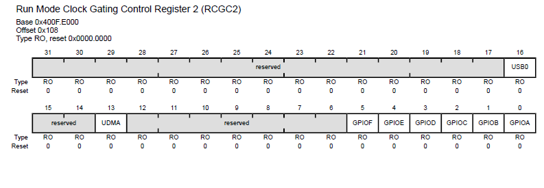
SYSCTL_RCGC2_R |= 0x00000020;- Adding
delay = SYSCTL_RCGC2_R;will delay the next instructions until the port clock is ready -
volatile unsigned long delay;is added within the routine/function
b) Setup PF2 as digital output:
- Set bit 2 in the GPIODIR register to make it an output

GPIO_PORTF_DIR_R |= 0x04;
c) Disable alternative function on PF2:
- Clear bit 2 in the GPIOAFSEL register to disable alternate functions

GPIO_PORTF_AFSEL_R &= ~0x04;
d) Setup PF2 as a digital I/O:
- Set bit 2 in the GPIODEN register to make the pin digital enabled

GPIO_PORTF_DEN_R |= 0x04;
e) Disable analog mode on port f:
- Write a 0 in the GPIOAMSEL register to disabled analog mode function

GPIO_PORTF_AMSEL_R = 0;
f) Configure PF2 as GPIO
- Clear bits 8:11 (PMC2) in the GPIOPCTL register to disable peripheral control for PF2 (all GPIO pins are configured as GPIO by default)

GPIO_PORTF_PCTL_R &= ~0x00000F00;
Setting the [INTEN] bit in the STCTRL register will "flag" the SysTick_Handler vector when ever the STCURRENT register is decremented to 0 (zero). This means that anytime STRCURRENT decrements to 0 (zero), the function/ISR below will be called by the interrupt vector. How this is setup is described below.
void SysTick_Handler(void){
  GPIO_PORTF_DATA_R ^= 0x04;       // toggle PF2
  Counts = Counts + 1;
}-
Adding startup.s: to your project allows you to use pre-defined vector tables for your ISRs.
-
Find the SysTick handler in the vector table (within startup.s)

- Notice that its vector name is
SysTick_Handler. You can use this name to define an ISR:void SysTick_Handler(void)in your program.
- Toggle PF2 when the the ISR is called via hardware interrupt.
- Toggle bit 2 in the GPIODATA register

GPIO_PORTF_DATA_R ^= 0x04;- Add a counter to keep track how many times SysTick invoked the periodic interrupt:
Counts = Counts + 1;
Reminder: Interrupts are called/invoked by a hardware event, rather than software call (ie: function();). This is why you dont see the SysTick_Handler() called anywhere in the program. The interrupt vector is responsible for interrupting the foreground thread. The code below explains how this works.

int main(void){
   Counts = 0;

   // System Initialization Routine
   PortF_Init();         // (a) initialize portf config
   SysTick_Init(16000);  // (b) initialize SysTick timer
   EnableInterrupts();   // (c) clear I bit (global enable)

   // Program routine
   while(1){
      WaitForInterrupt();// (d) place the CPU on low power
  }
}
(a) Initialize Port F:
- Setup the port initialization for the SysTick timer
PortF_Init();
(b) Initialize the SysTick timer:
- Algebraically calculate the value for the argument that SysTick_Init('arg') must take in order to delay the process for 1ms (this argument gets passed to the STRELOAD register on initilization):
- STRELOAD * [(1/System Clock)] = 1ms
- STRELOAD * [(1/16MHz)] = 1ms
- STRELOAD * 62.5ns = 1ms
- STRELOAD = 1ms/62.5ns
- STRELOAD = (1^-3)/(62.5^-9)
- STRELOAD = 16,000
- STRELOAD * 62.5ns = 1ms
- STRELOAD * [(1/16MHz)] = 1ms
SysTick_Init(16000);
- STRELOAD * [(1/System Clock)] = 1ms
(c) Enable Global Interrupts:
- Clearing the I bit (global interrupt bit/ I = 0) will enable Interrupts for this program.
void EnableInterrupts(void);EnableInterrupts();
(d) Wait on Low power:
- The WaitForInterrupt() call will put the CPU in low power mode while it waits for an interrupt to be invoked.
void WaitForInterrupt(void);WaitForInterrupt();