Home

Check the Bill of Materials for all of the parts needed.
A sample mt32-pi.cfg is included in this repository, the options that are
different from the default settings are:
# [midi]
# Disable USB input for faster boot time
usb = off

# [audio]
# Output audio to the GY-PCM5102 i2s board
output_device = i2s

# Initialise the GY-PCM5102 DAC on boot
i2c_dac_init = pcm51xx

# [control]
# Use the rotary encoder + 2 buttons control scheme
scheme = simple_encoder

# [lcd]
# Use the ssd1306 driver for the i2c OLED display
type = ssd1306_i2c

# invert the display since it's mounted upside-down in the Minisynth 32
rotation = inverted
- The generic 0.91" SSD1306 OLED also works with
height = 64, and gives a sharper but smaller text display. The defaultheight = 32is stretched but easier to read. - The generic rotary encoder I used works fine with the
encoder_type = fullsetting. - Be sure to check the mt32-pi documentation for setting up the required MT-32 ROMs and/or GM soundfonts, and other options you may be interested in.
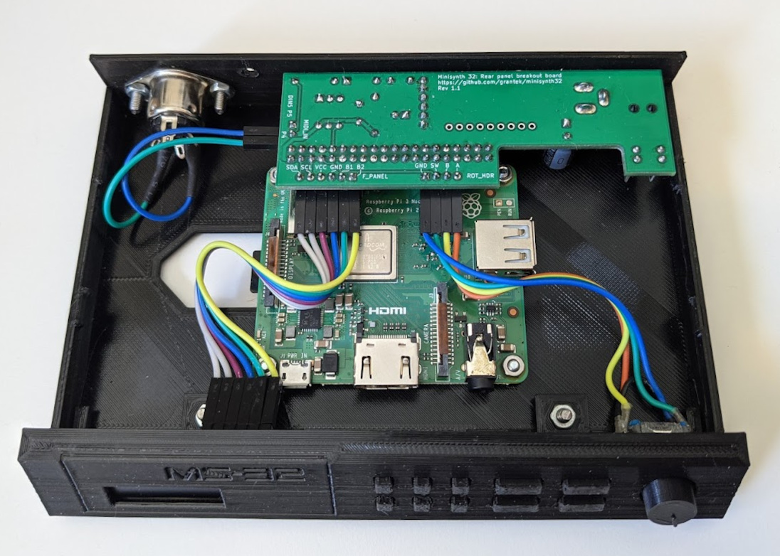
The rear I/O panel is designed to accept a standard MIDI signal for MIDI input, and the traditional connector for this (as on the Roland MT-32) is a 180 degree DIN5 socket.
The "base-din.stl" base uses a panel-mount DIN5 socket (mounted on the inside) connected directly to the input pins on the rear I/O board.
This is the most flexible setup, allowing you to plug in a MIDI cable from a retro computer or keyboard, or any modern computer with a USB to MIDI cable.
The "base-mcu.stl" base allows you to mount a small Arduino-based microcontroller board in place of the DIN socket. Using the MIDIUARTUSB sketch (a cut-down version is included in this repo), the microcontroller acts as a USB to MIDI cable, with the TX and 5v lines connected to the rear I/O board.
This allows you to connect the Minisynth 32 to a modern computer (or eg. to a MiSTer) with nothing more than a USB cable
If you can't decide which version to make and don't have a USB to MIDI cable, consider the DIN version, and make your own external USB to MIDI cable with an Arduino, some resistors, and a DIN plug. Commercial cables can be found cheaply, but the cheapest use chips that don't fully implement the MIDI standard, and won't transmit the SYSEX messages required for MT-32 compatibility reliably.
If using the USB base, the microcontroller board is clamped down against the base with a plastic clip. The clip is intended to be used with foam mounting tape to add some soft pressure to keep the board in place. If you're not using tape or need to adjust the height of the clamp otherwise, open the "mcuclamp.FCStd" model in FreeCAD, and adjust the "height of board + padding" field.
The length of the clamp can also be adjusted to suit different boards.
The hardware interface to mt32-pi currently only uses 2 buttons for interacting with the software. The Minisynth 32 has a slightly more authentic 10-button faceplate, with only 2 of the buttons functional and wired to the Raspberry Pi (these are the rectangular buttons in the "Sound" and "Sound Group" positions on the MT-32).
The 10-button version of the faceplate ("face.stl" and "buttonsheet.stl") uses 10 tactile switches to make each button "clickable", even though only 2 are functional.
The 2-button version of the faceplate ("face-2but.stl" and "buttonsheet-2button.stl") has clickable buttons in the "Sound" and "Sound Group" positions, and 8 hard-printed buttons on the face model.
The 10-button version is recommended because it's easier to print (and tiny clickable buttons are awesome), but the 2-button version is an option if for some reason you prefer it.
The 0.91" SSD1306 OLED boards aren't a branded standard, and depending on their construction they may have different thicknesses. This is due to how the glass screen is bonded to the PCB. Some use glue or thin tape to stick the glass to the board, and some use a foam adhesive tape which is a bit thicker.
There is clearance between the Minisynth 32 front panel PCB and the inside of the face plate to use a slightly thicker OLED board (you don't have to disassemble and re-glue it), but to allow for different thicknesses (and to keep the front PCB shorter than 100mm), there is a customiseable 3D-printed shim that attaches to the front PCB and helps with soldering the OLED board.
The "shim-2mm.stl" is used for an OLED board with the glass directly bonded to the PCB, and thinner shims can be used if you have an OLED board with some space between the glass and the PCB.
See the front panel PCB section below for fitting notes. If you need to adjust the thickness, open shim.FCStd in FreeCAD, open the spreadsheet named "vars", and edit the value of "shim thickness", then export the shim model as an STL.
There are 2 PCBs required, the Raspberry Pi hat that the rear connectors are mounted onto (the "rear I/O breakout board"), and a mounting board for the front panel. The "front" of the rear board faces downwards, so the components hang upside down to fit in the tight clearance of the case. The MIDI port is panel-mounted to the case for the same reason.
The KiCad project is based on a combined board with both PCBs joined by mouse- bites, so they can be ordered as a single panel. There are also files for the individual front and rear boards, because it was cheaper for me to order them this way from the PCB manufacturer I used (there was an extra fee for "panelised" boards that was more than double the base cost of a single small board).
PCB notes for manufacturers:
- Rear PCB only (v1.1): 31.7mm * 96mm
- Front PCB only (v2.0): 17mm * 96.2mm
- Panelised front+rear PCB: 51.3mm * 96.2mm
- Minimum hole size: 0.5mm (the standard "0.3mm" is fine to select)
- Minimum track spacing: 0.2mm (the standard "6 mils" is fine to select)
- Layers: 2
- Thickness: must be 1.6mm
I'm using a standard hobbyist FFF printer with black PLA filament. The face plate is kind of terrible for this kind of printing process due to the different angles involved, but I was successful in printing it upright at a 0.2mm layer height, with the visible layer lines horizontal in the finished part.
Specifically, use "tree" support for the face if your slicer has the option, which builds a tower of support starting on the build plate where possible and reaching across to the overhanging parts.
Regardless of the type of support, there will still be some on the inside of the faceplate, You need to be thorough in removing it from the inside floor of the faceplate because the front panel needs to fit in there, but there is some clearance so one or two layers of support stuck to the floor is okay. Careful use of a scalpel can help reach behind the PCB support behind the buttons.
The other parts are more straightforward to print, but read through the other sections for notes on customisation.
The shell was modeled in FreeCAD using the Part workbench, which uses simple geometric shapes added and subtracted from each other. If you want to modify the "MS-32" text on the face plate to something more authentic, select the Model window, press Ctrl-F to search the tree of objects, and search for ShapeString (the default name for a text object). In the Data window for the selected object you should be able to change the "MS-32" to something else, and press Enter. You may also need to supply the font file, I used the "TR-909" font freely available online.
If the faceplate doesn't update immediately, you should see a check mark on one or more objects in the tree. Right click on the top-level "face" object and select "Recompute object".
See the Choose your variant section for options here, you should have 10 or 2 tactile switches, and a 3D-printed shim to suit your OLED board.
If you're installing 10 tactile switches, solder these first, as it's easy to fit them all and then flip the board over with the PCB laying flat on them before soldering. It doesn't matter if the switches aren't perfectly aligned in rotation, as long as they're all flat against the PCB.
Take a 4-pin vertical header and solder it to the back of the OLED board, so that the plastic collar and long ends of the pins face backwards. Solder the short ends of the pins to the solder points on the front of the board, using the plastic collar on the back to keep them perpendicular.
If you're using a shim thinner than 1.6mm, you'll need to slide the plastic collar off the pins so that the OLED board can sit close to the front panel board (use a blade to start levering the collar backwards).
Clip the shim to the front panel board so that the flat section is on the front and the tab inside the shim's clip fits into the notch on the front panel board.
Ideally, do a test fit with the OLED board and shim by installing the board on top of the shim without soldering the pins onto the front panel PCB, and try fitting it into the front faceplate. If the PCB doesn't sit flush against the mounting hole on the faceplate without bending, the shim is too thick.

Test fitting different thickness displays and shims
Once you have a good fit, solder the pins in the front panel board and trim them.
Solder a 6-pin vertical header to the back of the front panel PCB in the
R_BREAKOUT position. The UNUSED headers are connected to the non-functional
buttons and don't need pins unless you're experimenting.

Assembled front panel PCB
The main soldering advice is to solder the DAC board first (see below), then the generic "lowest-height components first". Make sure to trim all legs on the underside of the rear breakout PCB, as this faces upwards and there isn't much room to the printed case.
IMPORTANT: As per the clumsyMIDI documentation, make sure that all 4 solder pad "jumpers" on the GY-PCM5102 board are set BEFORE soldering it to the board. To solder the GY-PCM5102 DAC board:
- Check the soldered pad headers on the rear of the GY-PCM5102 a final time.
- Solder a 6-pin header to the back of the board (on the short edge), and slide the plastic collar off, like the OLED board when using a thin shim.
- Solder the pins through the rear PCB. Alignment of the DAC board is less critical here, I used a 2-layer paper shim to help position it while soldering it.
- You don't need to solder anything to the row of 9 pins on the long edge, there is no connection to anything on the rear breakout board.
There are 3 pin headers on the rear breakout board that require a 90-degree angled pin header:
-
F_PANEL: connects to the front panel PCB, 6 pins. -
ROT_HDR: connects to the rotary encoder, 4 pins. -
MIDI_IN:: connects to the panel-mount DIN5 jack for MIDI input.
Check the clearance of your pin headers against the Raspberry Pi - if you have tall pin headers, push them down through the plastic collar so that they just have room for the jumper wires to connect.

Assembled rear I/O PCB
The rotary encoder used is a "12mm" generic device available online. Specifically, this is NOT a preassembled board with 5-pin header, there's not enough room for these, so you need to wire directly to the bare legs.
First, bend the mounting tabs on the encoder in against its base.

The pinout from the rear I/O board is labelled GND SW B A
- Take a 4-wire jumper cable (ie. with "DuPont" 2.54mm pitch female connectors), cut the connectors off one end, strip and tin the cut end of the wires.
- When soldering the cut ends to the rotary encoder, you can optionally use heatshrink to prevent the exposed legs from touching each other.
- Solder the
GNDwire to the middle pin of the 3-pin side, and from there (using another short piece of wire) connect it to one of the pins on the 2-pin side. - Solder the
SWwire to the other pin on the 2-pin side. - Solder the
Bwire to the pin on the left of the GND pin. - Solder the
Awire to the pin on the right of the GND pin. - If you get the
BandApins wrong, you can swap the jumper wires on the pin header of the rear breakout board.

Assembled rotary encoder
The 3D-printed knob for the rotary encoder can be hard to attach firmly. I found printing the knob in PET-G was best to get a firm fit, but PLA was less flexible, If the knob won't attach, you can carefully use a clean hot soldering iron pressed against the rotary encoder's shaft to soften the plastic in a similar way to the knurled screw inserts. If it's too loose, use some putty adhesive to hold it in place (this is much easier). There are a few STLs of different shaft widths, but the FreeCAD model is also easy to modify.
Make sure you have a good fit for the knob before assembling the face plate, but leave it off when inserting the rotary encoder.
This is similar to the rotary encoder, but it just requires 2 jumper wires soldered onto the panel-mount DIN5 jack. Looking at the face of the jack with the pins facing upwards, pin 4 is immediately to the left of the middle pin and pin 5 is on the right. Heatshrink isn't needed for insulation because the pins are so far apart, but I used heatshrink to add some mechanical stability to the connection.

Assembled MIDI port
This repository has 3D models to suit the Sparkfun Pro Micro board (an Arduino- compatible board), and the Arduino Micro board. The Sparkfun Pro Micro is recommended because it's shorter and doesn't interfere with the SD card port, but any of the Arduino boards that use the ATmega32U4 microcontroller will be compatible if you can fit it in (as mentioned in the intro, you can also leave the Arduino outside the box as a separate USB-MIDI adapter).
Configuring the Arduino IDE to upload the sketch is outside the scope of this project, see the links in the MIDIUARTUSB README. Things to note:
- Install the MIDI and MIDIUSB libraries in the Arduino IDE
- Install support for the Sparkfun board using the instructions at sparkfun.com
Once you've uploaded the sketch to the board, you need to add resistors and wires to the board. Solder a 220 ohm resistor onto each of the TX and VCC points (TX and 5v for the Arduino Micro), and solder DuPont wires in the way as the DIN port/rotary encoder.
If using a 3.3v microcontroller board, use a 33 ohm resistor on the VCC line and a 10 ohm resistor on the TX line.

Assembled (clone) Pro Micro microcontroller board
The Raspberry Pi is mounted using M2.5 bolts and nuts. M3 bolts may work (older versions of the base used M3 screws into threaded inserts), but require widening the hole slightly, which carries some risk of damaging the Pi.
The faceplate and MIDI port are attached using M3 bolts and nuts. The bolt lengths don't matter too much, 8-15mm is good. 8mm M2.5 bolts and nuts will also work here if you're purchasing one type of bolt.
The front PCB, rotary encoder, and top shell are attached using M3*4mm screws. M3 PC Case Screws may work here, but if they're any longer than 4mm, it's possible to push into the plastic resulting in a bulge on the front.
The mounting holes for the front panel PCB, and the top shell use 3mm M3 knurled threaded inserts. These are pushed into the (slightly narrower) mounting holes of the plastic case with a hot soldering iron to melt them into the hole (use a similar temperature as your 3D printer extruder, eg. 220-250 Celsius for PLA).
- Be careful you don't let the soldering iron touch the other 3D-printed parts!
- It's easy with a wide conical soldering tip to push the tip of the iron into the insert, and hold the insert down with tweezers while you remove the iron tip.
- Melt the first threaded insert into the faceplate as described above.
- Melt the other threaded insert into the mounting hole on the top shell while you're at it.
- The printed face plate is assembled with the assembled front panel PCB, the printed button sheet, and the printed knob on the rotary encoder.
- Drop the printed button sheet into the button holes, then fit the front panel PCB so that the tactile switches fit against the buttons, and the OLED display is aligned with the window. Attach the PCB with an M3 screw.
- Install the rotary encoder:
Remove the hexagonal nut and washer from the encoder, and simply screw the encoder shaft into the faceplate. There's a cutout in the faceplate to allow the encoder to spin, but pliers are helpful to rotate it carefully. You may need to keep screwing it into the plastic once it's in, and slightly strip away some plastic to get it to line up straight (you'll notice this when installing the knob).
If the encoder doesn't screw in tightly to the plastic face, put the hexagonal nut from the rotary encoder into the hexagonal relief in the front of the faceplate, then screw in the encoder. Even if you prefer to use the hexagonal nut regardless, screw the encoder into the plastic first to get it straight.

Assembled front face plate
- Format and prepare your Micro SD card for mt32-pi, and insert it into the Raspberry Pi. You can still access the SD card when the Pi is installed, but it's easier to do it beforehand.
- Attach the assembled Rear I/O PCB onto the Pi's 40-pin GPIO port, facing outwards.
- Line up the Pi on the base with the rear panel, and insert 4 M2.5 bolts through the base and mounting holes on the Pi. Secure with 4 M2.5 nuts, but do not over-tighten these as excess pressure can damage the Pi.
- Place the wired MIDI DIN jack on the inside of the base's rear plate, and attach with 2 M3 bolts from the outside (M3 nuts on the inside). The DIN5 jack is traditionally mounted with the pins facing down, and the alignment notch facing up. DIN5 cables have an an arrow at the alignment notch for easy attachment.
- Connect the DIN jack to the labelled pins on the rear PCB
MIDI_INheader. With the half-circle of DIN pins facing downwards, Pin 4 is left of the centre solder tab, and when connected to the rear PCB, the jumper wires won't cross.
Assembled DIN base
- Use a piece of padded foam adhesive tape to stick the microcontroller board onto the raised section of the base.
- Put a piece of padded foam adhesive tape on top of the ATMega32U4 chip to press against the clamp.
- Put the clamp over the MCU board and align the bolt holes.
- Use 3mm bolts and hex nuts to bolt the clamp down and secure the board.
- Connect the VCC/5v wire to Pin 4 on the rear I/O board, and TX to Pin 5.
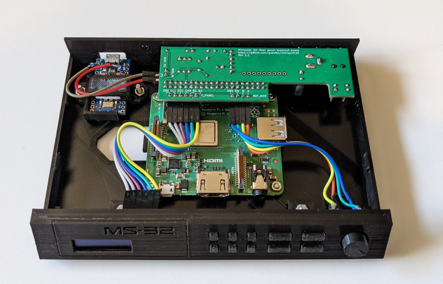
Assembled USB base with microcontroller board
- Connect the wired rotary encoder to the
ROT_HDRheader. - Use a row of 6 female-female jumper wires to connect the front panel's
R_BREAKOUTheader to the rear breakout board'sF_PANELheader. - Insert the face plate's tabs into the base, insert a bolt from the bottom of the base through each tab in the face plate and fasten with an M3 nut.
- Fit the top shell and fasten with an M3 screw.
- Stick 4 rubber feet (or felt pads, etc.) to the base to give clearance for the bolt heads.