I'd like to have a 3-axis CNC mill. I've considered buying one, but everything I can find violates one or more of the following constraints:
- Budget: It's going to be my first CNC mill, so spending a lot of money doesn't make much sense. The main purpose is to learn, and figure out what I actually need in a CNC mill. For that reason, I'd like to keep the budget below 1000€.
- Capability: At the same time, I don't want to buy a machine that I will outgrow within the first week. It should be capable of cutting aluminium.
- Space: I'm severely limited on space. It needs to comfortably fit on a desk.
- Environment: I don't have a proper workshop, unfortunately. The machine will need to run in my apartment, preferably without disturbing the neighbors.
There simply doesn't seem to be a machine like this, which is not a surprise. For this reason, I'd like to try and build my own, purpose-made for my use case.
I suspect it might simply be impossible to fulfill all of these requirements within the limited budget. If that is the case, I'm looking forward to learning what the limitations are specifically. I'm also aware that there's a high risk that a self-built machine will fall short in some or all of these areas. I think it's still likely to be a good investment, for the learning experience alone.
This project has stalled while in the planning phase. I was at the point where the calculations I wanted to do were way beyond my knowledge, so I had to do quite a bit of studying to make progress. Then my daily schedule shifted from under me and I was left with very little time to continue doing that.
I'm sure at some point, I'll have both the desire and the time to design my own CNC mill again. Whether I'll pick back up here when that time comes, or if I decide to start fresh, I don't know.
This project is open source. All documents, design files, and software in this repository are available under the terms of the Zero Clause BSD License (0BSD, for short). This basically means you can do anything with them, without any restrictions, but you can't hold the authors liable for problems.
See LICENSE.md for full details.
Here are some high-level design decisions I've made. None of them are final, and they might still change as I do more research:
- Configuration: Fixed gantry. The advantages are just too big, and I think I can live with a smaller work area in one axis.
- Size: 40x40x40 cm³ or thereabouts. Those are outer dimensions. If it turns out that this leaves not enough working area, I can go a bit larger, especially in height.
- Spindle: 1.5 kW air-cooled AC spindle. Should be strong enough to do well in aluminium and avoids the additional complexity of water-cooling.
- Axis motors: Stepper motors. I haven't really looked into servos, but seeing how many machines run just fine with steppers, I'm pretty confident they will work for me. An open-loop control system will also reduce cost and complexity.
- eBay
- Zhong Hua Jiang 1.5 kW Air-Cooled CNC Spindle Motor 80mm: Those are widely available on eBay. Preferably ER16, but ER11 is acceptable.
- 1.5 kW Huanjang VFD: there are sets of those and the aforementioned spindle available
- Sorotec
- Spindle Clamp: Lots of the spindle/VFD sets on eBay come with a clamp, but those don't have mounting holes. This one looks nicer.
These are the notes from my research process.
It's going to make sense to take inspiration from other machines at some point. Here are some links:
- OpenBuilds: Lots of machines of all kinds.
- MPCNC: Interesting design. Less traditional than what I have in mind.
- Tormach xsTECH: Really interesting machine, in terms of configuration, form factor, and enclosure. Pretty much what I want to build, but hopefully I can fit some more rigid components into the budget.
- PrintNC: Moving gantry design with a frame based on steel tubing.
- Millennium Mill: C-frame mill based on aluminium extrusion.
- ULTIMATE Bee: Classic moving gantry design, with what looks like high-quality components.
- PocketNC: 5-axis desktop CNC mill. Interesting, in that it is used for milling aluminium (easy to find examples on YouTube), but has a relatively weak spindle (200W).
- Nomad: Pretty close to what I would like to build, in regards to the configuration, form factor, and enclosure. Notable for its weak spindle (70W).
I'm looking into two groups of online shops:
- Local (i.e. European) shops, because that gives me a minimum of hassle (shipping, customs).
- Shops on platforms like AliExpress or eBay with low prices, as that might be necessary to meet my budget.
European shops:
- cnc-technics:: Have lots of relevant products, but probably too high-end for my budget.
- DOLD Mechatronik: Have a lot of different stuff, including aluminium in various sizes. At least some categories seems to be high-priced, relative to the available budget.
- Sorotec: Large selection of all kinds of stuff required for CNCs.
- MISUMI: Large selection of materials, mechanical components, and much more. Lots of options for modifying material and aluminium extrusion parts.
- Motedis: Materials and mechanical components.
AliExpress:
- Bulk Man 3D (also have a website): Large selection of lots of things I'm going to need.
- Makerbase: Control boards mostly seem not applicable, but the stepper drivers are very interesting.
- Zhong Hua Jiang: They manufacture spindles that they sell there, as well as other useful things.
eBay:
- motor-mall: Chinese shop, ships from Europe. Has spindles and VFDs.
- Those seems to be essentially the same:
- chinacnczone-de
I believe that the following machine configurations are the strongest contenders:
- Moving gantry: Tool moves in all 3 axes.
- Fixed gantry: Tool moves in x and z axes, table moves in y axis.
I have ruled out more exotic configurations for my first build (despite having lots of ideas), to reduce overall risk.
References:
- https://cncchronicle.com/fixed_or_moving_gantry_for_cnc_router/
Compares the two configurations. Has a nice comparison table further down.
I see two potentially viable ways to go, regarding the spindle:
- Cheaper DC spindle, around 500W.
- Mid-range AC spindle, possibly water-cooled.
Advantages of DC spindles:
- There are examples of machines with relatively weak spindles that can definitely mill aluminium, although not fast and with not-so-great surface finish. It might be enough for my needs.
- Cheaper than AC spindles.
- More compact than AC spindles. That doesn't just go for the spindle itself, but also for the hardware needed to control it (a possibly bulky VFD, in the case of AC spindles). Given the size constraints, this is very attractive.
- No dealing with AC power.
Examples of machines with relatively weak DC spindles:
- PocketNC: Both the V2-10 and the V2-50 come with a 200W spindle12. And yet it seems capable milling aluminium and more. This video is very interesting: https://youtu.be/7YfRNZbfjaY?t=326
- Nomad: Only has a 70W spindle. It's easy to find videos of it milling aluminium, but in the one's I've seen, either the sound is covered by a voiceover, or it sounds horribly chattery. So not a strong case, but interesting none the less.
I think the PocketNC is a strong example here. It's obviously not capable of great speeds, and it starts chattering if the settings are too aggressive. But still, it seems to be capable of producing aluminium parts.
Examples of DC spindles:
- 104W, 10.8k RPM, ER8, ~140€; includes driver and bracket
- 400W, 12k RPM, ER8, ~130€; includes driver and bracket
- 400W, 12k RPM, ER8, ~140€; includes driver and bracket
- 500W, 12k RPM, ER11, ~120€; includes driver and bracket
- 500W, 12k RPM, ER11, ~60€; includes driver and bracket
- 600W, 12k RPM, ER11, ~85€; motor only
Advantages of AC spindles:
- They are simply more powerful. I found information, that 1kW power and 24k max RPM should be good for milling aluminium, and I think everything in that range is an AC spindle.
- Water-cooled AC spindles are pretty common. Those are quieter and more long-lived, and I've been told that water cooling isn't too bad, from a complexity perspective.
- The Chinese ones are still surprisingly affordable, although I have no idea how the quality compares to more expensive ones.
Notes:
- In articles I've read, Huanyang has been called out as a quality brand, and I can find affordable offers with EU-based inventory. Unless the budget turns out to be really tight, or some other information comes to light, I might just go with that.
- Some spindles come in a rectangular form factor, with mounting holes included. Seems more convenient than the round ones.
Examples:
- Air-cooled:
- 0.8kW, 24k RPM, ER11, ~240€; VFD included
- 0.8kW, 24k RPM, ER11, ~240€; VFD specified at 1.5kW
- 2.2kW, 24k RPM, ER20, ~220€; VFD included
- 2.2kW, 24k RPM, ER20, ~220€; VFD included; not sure, if there's any difference to the previous one
- Water-cooled:
- 1.5kW, 24k RPM, ER16, ~155€; spindle only
- 2.2kW, 24k RPM, ER20, ~320€; full set: spindle, VFD, water pump, holder, collets
- 2.2kW, 24k RPM, ER20, ~350€; VFD included
- 3.0kW, 24k RPM, ER20, ~165€; spindle only
- 3.0kW, 24k RPM, ER20, ~285€; VFD included
- https://mellowpine.com/cnc/how-to-choose-a-cnc-spindle/
Has very specific recommendations. - https://mellowpine.com/cnc/best-cnc-spindles/
Presents some specific spindles and what they're suitable for. - https://en.wikipedia.org/wiki/Collet#ER_collets
Just some background info on ER collets, for the mechanically challenged (like me). - https://www.youtube.com/watch?v=w26DHMccicE
Upgrades to a 3018. Performance becomes satisfactory with a ~1kW spindle. 500W works, but is really slow.
Based on everything I've seen, I've narrowed the spindle selection down to the following criteria:
- 1KW+: Yes, you can mill aluminium with less, but it's far from certain whether the results would be satisfying.
- 24,000 max. RPM: This should be sufficient for my needs, and it seems that within the category of 1kW+, this doesn't further reduce the selection.
- Air-cooled: I can find a few (very few) water-cooled ER16 spindles on eBay, but at this point, I'm happy to accept the reduced complexity. Any difference in noise is probably irrelevant anyway, compared to the milling noise itself.
- AC: I can't find any DC spindles that are powerful enough, so it's not a choice at this point.
Most of the spindles I can find with these parameters are from this manufacturer: Zhong Hua Jian
They have a square spindle that I would prefer: 1.5KW 1500W Air Cooled Spindle Square CNC Spindle Motor ER11/ER16
Unfortunately that's the one that I can't find a source for around here.
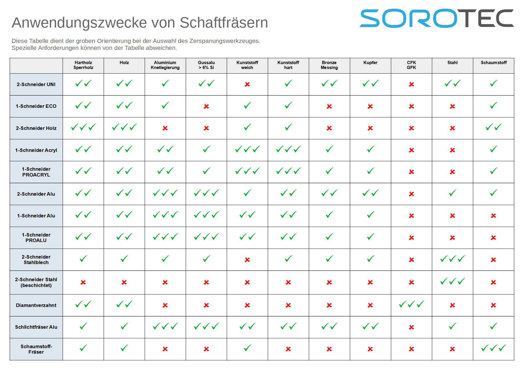
The cutting tools that are expected to be used are important for various design decisions. Since I don't have very specific use cases in mind, my goal here is to get a feel for the range of tooling that I might want to use for aluminium. From there, I'll hopefully have better information to make various design decisions.
Here are some cutting tools that I could find:
- cnc-technics
- Dold Mechatronik
- Sorotec: https://www.sorotec.de/shop/Zerspanungswerkzeuge/
- Datron: https://webshop.datron.de/industrie-fraeswerkzeuge/?p=1
- Misumi: https://de.misumi-ec.com/vona2/fs_machining/
I've decided to focus my analysis on the Sorotec offerings, as they have a broad selection, and also focus on the class of machine I'm trying to build, roughly. I'm only looking at tools that are specifically recommended for aluminium.
Analysis:
- Diameter, cutting (mm): 0.2 - 60
- Diameter, shaft (mm): 3 - 12
- Length, cutting (mm): 2 - 43
- Length, total (mm): 38 - 110
List of tools taken into account:
- Countersinking
- Deburring/Chamfering/Filleting
- Drilling
- Engraving
- https://www.sorotec.de/shop/Zerspanungswerkzeuge/sorotec-werkzeuge/Gravurwerkzeuge/Gravierfraeser/
- https://www.sorotec.de/shop/Zerspanungswerkzeuge/sorotec-werkzeuge/Gravurwerkzeuge/Gravierstichel--Standard-/
- https://www.sorotec.de/shop/Zerspanungswerkzeuge/sorotec-werkzeuge/Gravurwerkzeuge/Radienstichel/
- Face Milling
- Finishing
- Milling
- https://www.sorotec.de/shop/Zerspanungswerkzeuge/sorotec-werkzeuge/1-8-werkzeuge/3-175----1-8---Fraeser/2-Schneider-ALU/
- https://www.sorotec.de/shop/Zerspanungswerkzeuge/sorotec-werkzeuge/1-8-werkzeuge/3-175----1-8---Fraeser/Sonderlaengen-360/2-Schneider-361/
- https://www.sorotec.de/shop/Zerspanungswerkzeuge/sorotec-werkzeuge/1-schneider/Schaftfraeser-ALU-412/
- https://www.sorotec.de/shop/Zerspanungswerkzeuge/sorotec-werkzeuge/1-schneider/1-Schneider-Sorotec-PROALU/
- https://www.sorotec.de/shop/Zerspanungswerkzeuge/sorotec-werkzeuge/1-schneider/einschneider-sorotec-alu-beschichtet/
- https://www.sorotec.de/shop/Zerspanungswerkzeuge/sorotec-werkzeuge/2-schneider/2-schneider-kurz/
- https://www.sorotec.de/shop/Zerspanungswerkzeuge/sorotec-werkzeuge/2-schneider/2-schneider-alu-eckradius/
- https://www.sorotec.de/shop/Zerspanungswerkzeuge/sorotec-werkzeuge/2-schneider/Schaftfraeser-ALU/
- https://www.sorotec.de/shop/Zerspanungswerkzeuge/sorotec-werkzeuge/RADIENFRAeSER/1-Schneider-PRO/
- Tapping
Additional notes:
- https://www.sorotec.de/webshop/Datenblaetter/fraeser/schnittwerte.pdf
- https://webseite.sorotec.de/download/fraesparameter/schnittwerte_1_8_sv.pdf
- https://www.sorotec.de/webshop/Datenblaetter/fraeser/fraeser_verwendung_schaftfraeser.png
- https://webseite.sorotec.de/download/fraesparameter/schnittwerte_planfraeser.pdf
The following is based on some research, and my own not-that-great knowledge about mechanics. For all I know, my complete reasoning could be wrong.
My thinking is that once I've selected a spindle, I can calculate what maximum cutting force can be achieved using that spindle. With that information, I can then decide how to dimension the linear axes and the frame.
Some reference material on how to calculate cutting force:
- Cutting Forces in Milling
- Understanding tangential cutting force when milling
- Lots of useful formula for milling
From the aforementioned references, I got the following formula for computing tangential cutting force:
Where:
-
$F_t$ : tangential cutting force -
$T_S$ : spindle torque -
$R$ : cutter radius
Which makes a lot of sense. I can hopefully get the maximum torque rating of the spindle from the manufacturer. If not, I'm sure there's a way to calculate torque from spindle power, but I haven't looked into how to do that.
Given the maximum torque, I can put in the radius of the smallest tool I intend to use. It's quite possible that the resulting force will be larger than the small tool can withstand. But I can just put in larger and larger tools until I get a force that will actually work with the tool, thereby figuring out the maximum tangential cutting force that is actually realistic.
Once I have that number, I need two more:
- Maximum expected tool length
- Distance between tip of maximum length tool and spindle holder.
With that, I can calculate the moment that acts on the spindle, which I can then use to figure out how to dimension the linear hardware on the z and x axes.
At this point I'm realizing that it would be easier to just do the calculations instead of spelling out how I would do them. I can't though, because I haven't selected a spindle yet, so I'll continue writing out my thoughts on this, so I don't forget between now and when I'll actually do the calculations. (When I started writing this, I just expected there would be much more research and much less reasoning.)
Side note: It's interesting to note that the worst case for max. tangential cutting force is a thin tool, and worst case for max. moment on the spindle is a long tool. It's probably a good idea to plug in multiple tools into the whole calculation, to figure out where the actual worst case is, since the thinnest tool certainly won't be the longest.
Based on the max. tangential cutting force, I can also figure out the maximum moment that acts on the y axis, and dimension the linear hardware for that too.
I assume with all those moments calculated, I can then figure out what the frame would need to look like to not deflect too much under that level of stress. I don't know how that works though.
I figure that within the constraints of a home-built machine, linear rails are the best I can practically do in this category. I've decided to focus my research on those, and see where that leaves me budget-wise. I'll revisit later, if necessary.
Information from online shops:
- ARC/HRC: https://www.dold-mechatronik.de/Profilschienenfuehrungen-ARC-HRC
- data sheet: https://www.dold-mechatronik.de/documents/Datenblaetter/Linearfuehrungen/Datenblatt-Linearfuehrung-ARC-HRC.pdf
- seal (Dichtung): S or B
- S: seals better; recommended for dirty environments.
- B: less friction
- preload (Vorspannung): VC, V0, V1, V2
- VC and V0 have play; only available in lower quality classes (H, N)
- V1 and V2 don't, but have more friction
- V1 might be a good compromise, is my initial impression
- HRC has higher tension than ARC, in the equivalent classes
- precision class (Genauigkeitsklassen): N, H, P, SP, UP
- recommended for CNC mills: N to P, or H to SP for more precision
- bearing cage (Kugelkette): should make sure it's included, unless price is prohibitive
- standard lengths, minimum: 300mm
- series:
- ARC-M: compact, narrow
- I assume I'll have two rails in every axis, so narrow carriages should be fine. I assume broader ones make sense, if you have just one rail.
- ARC-F: compact, flange
- broader than M
- HRC-M: high, narrow
- more height above the rail
- HRC-F: high, flange
- relates to HRC-M as ARC-F relates to ARC-M
- ARC-M: compact, narrow
- sub-series: Each of the previously presented series is further divided into more series. The distinction between those is the size of the carriage that fits a given size rail. Larger ones can take more force.
- ARC-MS (S = small?): rail sizes from 15x15 to 28x27
- ARC-MN (N = normal?): rail sizes from 15x15 to 53x46
- ARC-ML (L = large?): rail sizes from 15x15 to 53x46
- BR: https://www.dold-mechatronik.de/Profilschienenfuehrungen-BR-Serie
- Can't find a data sheet.
- BR9 and BR12 available.
- Only BR12 has some dimensions in the shop. Smaller compared to even the smallest ARC/HRC.
- Sold in sets of one rail + 2 carriages, which is what I need anyway.
- Probably not interesting to me, given the small size and lack of information compared to ARC/HRC.
- HG:
- shop links:
- DOLD Mechatronik
- HIWIN
- https://www.sorotec.de/shop/CNC-Mechanik/lineartechnik/Lineartechnik--Hiwin/Fuehrungswagen/Baureihe-HGH-247/
- https://www.sorotec.de/shop/CNC-Mechanik/lineartechnik/Lineartechnik--Hiwin/Fuehrungswagen/Baureihe-HGW/
- https://www.sorotec.de/shop/CNC-Mechanik/lineartechnik/Lineartechnik--Hiwin/Fuehrungsschienen/Baureihe-HGH/
- Sorotec
- data sheet: https://www.dold-mechatronik.de/documents/Datenblaetter/Linearfuehrungen/Datasheet_HGH-HGW_de_210720_Dold.pdf
- DOLD Mechatronik data sheet is much less detailed than ARC/HRC
- HIWIN has much more detailed information. See below.
- Size seems comparable to lower range of ARC/HRC, which I think fits my use case.
- shop links:
- LF: https://www.dold-mechatronik.de/Profilschienenfuehrungen-LF-Serie
- Sizes seem comparable to lower end of ARC/HRC.
- Barely anything available at DOLD Mechatronik.
- The available rails are way too long.
- Not data sheet.
- LSK: https://www.dold-mechatronik.de/Profilschienenfuehrungen-LSK-Serie
- data sheet: https://www.dold-mechatronik.de/documents/Dold_LSK_Linearfuehrungen.pdf
- Sizes seem comparable to lower end of ARC/HRC.
- FL and GL recommended for machine tools.
- FL seems lower, possible better suited.
- pretention (Vorspannung): Z2 (hightest) recommended for machine tools
- more information in there I didn't go through in detail
- unclear how this is meaningfully different from ARC/HRC
- MGN:
- shop links:
- DOLD Mechatronik
- Sorotec
- much smaller; probably more suited to low-force stuff like printers
- shop links:
- MGW: https://www.dold-mechatronik.de/MGW-Miniatur-Linearfuehrungen-breit
- MGN, but broad
- probably unnecessary, compared to MGN, since I'm going for two rails per axis
- MR: https://www.dold-mechatronik.de/MR-Miniatur-Linearfuehrungen
- data sheet: https://www.dold-mechatronik.de/documents/Datenblaetter/Linearfuehrungen/Datenblatt-Miniaturlinearfuehrung-MR.pdf
- very small, comparable to MGN/MGW
- nice data sheet, didn't look into it in detail
- didn't see anything about applications; probably too small for a mill
- MRW: https://www.dold-mechatronik.de/MRW-Miniatur-Linearfuehrungen-breit
- same data sheet as MR
- wide version of MR
- MSB: https://www.dold-mechatronik.de/Profilschienen-MSB-Serie-PMI
- data sheet: https://www.dold-mechatronik.de/documents/Datenblaetter/Linearfuehrungen/MSB-TE-E.pdf
- data sheet is sparse
- size comparable with lower end of ARC/HRC
- ST: https://www.dold-mechatronik.de/ST-Miniatur-Kurzhub-Linearfuehrung
- shares a data sheet with MRW
- specialized thing for short movements; probably not interesting
Information from HIWIN:
- full catalogue with lots of information:
- https://www.hiwin.de/medias/GW-11-4-EN-2207-K.PDF?context=bWFzdGVyfGhpd2luRG9jdW1lbnRNZWRpYXw3NjY2NzMwfGFwcGxpY2F0aW9uL3BkZnxoaXdpbkRvY3VtZW50TWVkaWEvaDZkL2hkNi85MjcwNzkzNTY4Mjg2LnBkZnxmMjBjMGQ1ZjFjODA0ZjY5ODQ1Y2UwZWY5NGY5YWIzZWIxNGUzZTU3M2JjMmQ5OGVlOTMzZjQ4YmE3YjU5YmJh&attachment=true
- https://www.hiwin.de/medias/GW-11-4-DE-2207-K.PDF?context=bWFzdGVyfGhpd2luRG9jdW1lbnRNZWRpYXw4MjA1ODI3fGFwcGxpY2F0aW9uL3BkZnxoaXdpbkRvY3VtZW50TWVkaWEvaDZiL2g2Ni85MjcwNzkzNTM1NTE4LnBkZnwzNDVmMDIxNDRjNDY4ZDUxOTVmNTgzN2M5ZjgwNzAwYzRlMGEyNmVlNmRjOGRlOWViZGQ0ZWI0OTMyMGI2N2U0&attachment=true
- configurator: https://www.hiwin.de/configurator/newConfiguration/easyKAT_GW
Conclusions:
- ARC and HG seem like good options, given the size and available documentation.
- Especially the HIWIN documentation is nice. But in the Sorotec store, HIWIN is also twice as expensive as the Sorotec-branded stuff.
I would need, per axis:
- 2 rails
- 4 carriages
So 6 rails and 12 carriages overall.
Open questions:
- What type should I go with?
- Is HIWIN even an option price-wise? Would it be even worth it? Go for something cheaper?
- What size rail?
Much like with linear rails, I figure that the best I can practically do on linear actuators are ball screws. I will do my research on that, and might scale back to something cheaper, if it turns out to be necessary.
References:
- Catalogue from HIWIN
- https://www.hiwin.de/medias/BS-08-10-DE-2206-K.PDF?context=bWFzdGVyfGhpd2luRG9jdW1lbnRNZWRpYXw2Mjg5NTAzfGFwcGxpY2F0aW9uL3BkZnxoaXdpbkRvY3VtZW50TWVkaWEvaDg3L2hmYi85MjcwMzA0NDczMTE4LnBkZnxlMzgzMWVjMzQ0NTAxOTQ2NWViYjJiMDQwN2VkMTI4MjdhYTNhNWViMTU5MGJmNGFmNDA1MjA2MWVjNGZiMzlm&attachment=true
- https://www.hiwin.de/medias/BS-08-10-EN-2206-K.PDF?context=bWFzdGVyfGhpd2luRG9jdW1lbnRNZWRpYXw2MzM0NjAyfGFwcGxpY2F0aW9uL3BkZnxoaXdpbkRvY3VtZW50TWVkaWEvaGViL2g5Mi85MjcwMzA0NTA1ODg2LnBkZnw1Yzk3MzcxZTc1YmUyZTgzYjJmMWQxOGJkYzI1YTNjNTFkNGQwOWY1MGE3MGVjODg2OWNjNjBmNGI5NTFmNjBh&attachment=true
Notes:
- HIWIN:
- types
- rolled
- diameter: 8-63mm
- typical application: transportation
- accuracy: T5 - T10
- less friction and quieter than standard threads
- nuts
- FSIDIN, FSCDIN: flange
- RSI, RSIT: no flange; probably wrong for my use case
- peeled
- diameter: 16-80mm
- typical application: transportation + positioning
- accuracy: T5 + T7
- nuts
- DEB-x
- flange
- single nut
- variants with different kinds of wipers
- DDB-x
- flange
- double nut
- variants with different kinds of wipers
- ZE, SE
- no flange
- probably wrong for my use case
- SEM
- safety nut
- has some redundancy; correct function guaranteed up until certain play
- pretty sure I don't need this
- DEB-x
- ground
- diameter: 6-100mm
- typical application: positioning
- accuracy: T0 - T5
- no stock; only available upon request
- nuts
- FSC
- flange
- single nut
- cassette recirculation
- FDC
- flange
- double nut
- cassette recirculation
- FSI
- flange
- single nut
- internal recirculation
- FDI
- flange
- double nut
- internal recirculation
- RSI, RDI
- no flange
- probably unsuited
- FSC
- other, seemingly more specialized types available
- rolled
- preload needs to be balanced
- too low: lacks rigidity
- too high: more friction, reduced service life
- selection: page 12 of the HIWIN catalogue has a step-by-step guide
- ball recirculation systems
- external: tube outside of the nut body
- internal: tube within the nut
- cassette: internal, but somehow different? don't understand the description
- wipers
- NBR (N): "used in almost all applications"
- NBR-finger (K): more friction, more resistance against dirt and chemicals
- felt (F), felt-finger (V): different attributes, but unclear on applications
- precision
- T0 is best; don't have a feel for the numbers
- the better the accuracy, the more limited length is; not relevant for my application
- recommendations for milling
- x/y axes: T1-T5
- z axis: T2-T5
- play/preload
- rolled and peeled are delivered with play by default
- types of preload
- preloaded single nut: ball size
- lead offset: not suited for high preloads or high leads
- preloaded double nuts: distance between nuts
- preload should not exceed
- 5% of dynamic load rating for single nuts
- 10% of dynamic load rating for double nuts
- should only be preloaded when absolutely necessary
- load rating
- Cdyn: load at which 90% of ball screws reach life expectancy of 1 million revolutions
- C0: load which causes permanent deformation of more than 0.0001 ball diameter
- drive torque: calculation formulas on page 28
- shaft ends
- B, E, F: simple transport applications, low axial forces
- SFA, SLA: more challenging precision applications
- SLA: supported bearing (S1, S11, S5)
- for supporting the non-motor end of the ball screw?
- SFA
- fixed bearing (S2, S22, S3)
- for supporting the motor end of the ball screw?
- SLA: supported bearing (S1, S11, S5)
- WBK: heavy duty
- housing for flange nuts
- suitable for DEB-x, DDB-x, FSCDIN
- types
Looks like I need, per axis:
- ball screw
- flanged nut
- supported bearing
- fixed bearing
- flanged nut housing
Other than that, not sure yet, what conclusions to draw from all this.
Open questions:
- What size screw do I go with?
- What accuracy do I need?
- HIWIN is probably too expensive. Do cheaper options require different research?
- What about preload? The HIWIN data sheet makes it sound like preload should be avoided, if at all possible. But isn't the whole point of a ball screw to avoid backlash?
Warning: This section is more of a brain dump, and not based on actual research so far. I'm drawing my own conclusions based on things I've seen in the past, and I'm probably missing something.
I'm mainly thinking about two ways of building the frame:
- Aluminium extrusion
- Aluminium plates
Or a combination of the two. Aluminium extrusion has the advantage of being more flexible and easier to use, while plates would require at least somewhat accurate drilling, if not machining.
To make use of the full flexibility and simplicity of aluminium extrusion though, I need angle brackets to connect them. I don't know how well that would fare in regards to stiffness. I've seen people connect profiles by drilling through one, and putting in a screw that screws in the end of the other, but that would require somewhat accurate drilling again, plus cutting the profiles to length precisely.
I'm guessing connecting plates with screws would be plenty stiff, and I could probably buy them already cut to size. This would only leave the problem of drilling and tapping, which might be manageable. An advantage over extrusion might be that they are just denser. Since more weight is largely good in a machine frame, and space is at a premium, that would probably be an advantage.
At this point I'm thinking, I'll probably do a CAD design based on plates and see where that leads. If it seems doable, I might go that way. If not, I might reconsider doing an extrusion-based design.
Makerbase: https://www.aliexpress.com/store/1047297
- standard(?) breakout board pinout
- Makerbase MKS A4988: https://www.aliexpress.com/item/32888457440.html
2.0A max - Makerbase MKS TMC2208: https://www.aliexpress.com/item/32888980385.html
2.0A max - Makerbase MKS TMC2209: https://www.aliexpress.com/item/33043140087.html
2.5A max - Makerbase MKS TMC2225: https://www.aliexpress.com/item/4001149124672.html
2.0A max - Makerbase MKS TMC2226: https://www.aliexpress.com/item/1005002669282600.html
2.5A max
- Makerbase MKS A4988: https://www.aliexpress.com/item/32888457440.html
- Makerbase MKS TMC2160: https://www.aliexpress.com/item/1005004044381878.html
4.33A max - Makerbase MKS TMC2160-OC: https://www.aliexpress.com/item/4000185818422.html
4.33A max, extra cooling
On the controller side I have the following priorities:
- Resist the temptation to do any custom software, or otherwise use something exotic. This might be an option in later builds, but I want to keep it simple for the first version.
- Be controllable from a regular PC, without requiring one to run. I don't want to add a screen/keyboard/mouse to the bill of materials, but I also don't want to dedicate a whole computer to control it.
I found the following options:
-
LinuxCNC: Runs on the Raspberry Pi: http://linuxcnc.org/docs/stable/html/getting-started/getting-linuxcnc.html
The download page talks about interface cards. Not sure what specifically is required, but I found this list: http://wiki.linuxcnc.org/cgi-bin/wiki.pl?LinuxCNC_Supported_Hardware
I haven't done much research, but the interface cards I saw were quite expensive. Overall, I get the impression that LinuxCNC is not suited for a budget-sensitive build.
-
Machinekit: I found it hard to understand whether this is suitable. What I can gather is that it runs on the BeagleBone Black: https://www.machinekit.io/docs/getting-started/machinekit-images-for-bbb/
No idea what else is required to make it work. The information presented is not very approachable, and I'm not sure how much of it is outdated.
-
grbl: I've often heard about this being used for the kind of small-scale CNC machine I'm aiming to build. It's confusing though. There are two different repositories, neither actively developed, and lots of forks.
-
grblHAL: Fork of gbrl, for 32-bit MCUs.
-
FluidNC: Looks promising. Has a list of supported hardware: https://github.com/bdring/FluidNC/wiki/Hardware-that-Runs-FluidNC
Based on my cursory research into this area, I think this might be the wrong approach. It might be better to search for easily available CNC controllers, and figure out which software to use for them from there.
Host-side control software:
- https://github.com/Denvi/Candle
- https://github.com/winder/Universal-G-Code-Sender
- https://github.com/terjeio/ioSender
I'm currently operating under the assumption that an open-loop control system using stepper motors will be used, for cost reasons.
There is a huge number of options available. A lot of them are pricy enough to take up the majority of the available budget. For that reason, I'm focusing on lower-priced options.
TinyG control boards, which include steppers drivers, but lack something to control the spindle:
-
https://synthetos.myshopify.com/products/tinyg
Not the cheapest option ($129.99), but open source and well-documented. Includes 4 stepper drivers (2.5 amps). -
https://synthetos.myshopify.com/collections/assembled-electronics/products/gshield-v5
Cheaper alternative to the TinyG ($49.99), which requires an Arduino to work. I happen to have an Arduino Due lying around, so that might work out well. Includes 3 stepper drivers (2.5 amps).
Both of those boards don't seem to be available in Europe, so the real cost might be significantly higher, with shipping and customs duties.
SainSmart sells the controller boards for their low-cost CNC machines separately:
- https://www.sainsmart.com/collections/genmitsu-cnc-replacement-upgrade-parts/products/genmtisu-grbl-controller-board-for-3018-prover-3018-mx3
- https://www.sainsmart.com/collections/genmitsu-cnc-replacement-upgrade-parts/products/controller-board-for-genmtisu-cnc-router-3018-3018-pro-1810-rpo
They are much cheaper (40-50€) and can control a spindle. One of them is limited to 1.5-2amps for the stepper motors, the other doesn't specify. Since the SainSmart machines are pretty weak, it's doubtful that the controller board supports any motors (axis or spindle) that would be a significant upgrade over them.
Here's another board, linked to grblHAL: https://www.tindie.com/products/philba/grblhal-bob-unkit-for-teensy-41-t41u5xbb/
Costs around 50€, plus shipping from the US. Requires a Teensy 4.1, which is readily available locally, for under 30€. Doesn't include stepper drivers, but can control a spindler with an external VFD.
References:
- https://www.cnccookbook.com/cnc-controller-software-drivers-boards/ Overview over some available options.
As far as I can see, the machine needs the following kinds of power:
- 230V AC: Since I'm in Europe, this is the input I'm dealing with. It's needed by the VFD for the spindle, the DC power supply, possibly the water pump.
- 3.3V - 5V DC: This is the typical range for microcontrollers and many other kinds of electronics.
- Higher-voltage DC: The stepper motors are going to need DC at a higher voltage than the controller.
So I'm going to need a power supply that turns AC into DC, and possibly something else to step the DC up or down to meet the different requirements. As for the power supply, I've often seen Meanwell in various sets and such. Unless there's a good reason not to, I might just stick to that.
I'd love to use Fornjot, but it'll be a while before it's ready for a project like this. I hope that I can migrate the project to Fornjot eventually.
Normally, I'd favor open source software, but since migration to Fornjot at a later stage is planned anyway, I don't see that as a priority. I've used OpenSCAD, FreeCAD, SolveSpace, and other open source options in the past, and I'd like to take this opportunity to try something new.
I'm focusing the research on options that are free (or have a free tier) and support Linux:
- OnShape: Looks highly professional. Would certainly be an interesting learning experience.
- SketchUp: Also looks interesting, although the website presents architecture and furniture use cases, versus the mechanical assemblies showcased on the OnShape website. Hard to say how relevant this will be for this project.
- TinkerCAD: Looks least interesting, judging from the website, as it stresses the beginner/education use case. Doesn't mean that it won't be more than capable enough for this project though.
The design goal for the whole machine is to have it run in an apartment environment, if at all possible, without creating the kind of noise that would be unacceptable in such an environment. An enclosure is going to be critical to achieve that.
References: