Firmware Overview
- Overview
- User Commands
- AVR Ports
- Hardware Commands
- Breakpoint Register
- Address/Dout Register
- Data Multiplexer
- Target Specific Code
The firmware for each of ICE targets is build from the same source file: https://github.com/hoglet67/AtomBusMon/blob/master/firmware/AtomBusMon.c
There is some use of conditional compilation described in Compiling-firmware#target-specific-customizations
The firmware really just does the following:
- Reads a command line from serial input
- Parses the command line into a command and parameters
- Calls the command implementation
The command implementations are all prefixed by doCmd:
- doCmdBreakI
- doCmdBreakRdIO
- doCmdBreakRdMem
- doCmdBreakWrIO
- doCmdBreakWrMem
- doCmdClear
- doCmdContinue
- doCmdCrc
- doCmdDis
- doCmdFill
- doCmdHelp
- doCmdIO
- doCmdList
- doCmdMem
- doCmdReadIO
- doCmdReadMem
- doCmdReset
- doCmdStep
- doCmdTest
- doCmdTrace
- doCmdTrigger
- doCmdWatchI
- doCmdWatchRdIO
- doCmdWatchRdMem
- doCmdWatchWrIO
- doCmdWatchWrMem
- doCmdWriteIO
- doCmdWriteMem
The command implementations use the following AVR Ports to interact with the Bus Monitor hardware:
| Port | Bit Range | Direction | Function |
|---|---|---|---|
| A | 7..4 | In/Out | HD44780 LCD data |
| A | 3 | unused | |
| A | 2 | Output | HD44780 LCD enable |
| A | 1 | Output | HD44780 LCD read/notWrite |
| A | 0 | Output | HD44780 LCD register select |
| B | 7..6 | unused | |
| B | 5 | Output | Hardware command edge |
| B | 4..0 | Output | Hardware command data |
| C | 7..0 | unused | |
| D | 7 | Input | Event FIFO empty flag |
| D | 6 | Input | Interrupt switch (GODIL SW1) |
| D | 5..0 | Output | Multiplexor select |
| E | 7..0 | Input | Multiplexor data |
| F | 7..0 | unused |
The functionality for the HD44780 LCD is currently disabled in the VHDL projects, and #ifdefed out in the C source.
The operation of the bus monitor hardware is controlled through a command interface via PortB.
| Command | Param | Description | |
|---|---|---|---|
| 0x00 | CMD_SINGLE | 0 | Disable single stepping |
| 0x01 | CMD_SINGLE | 1 | Enable single stepping |
| 0x02 | CMD_BRKPT | 0 | Disable breakpoints (and watchpoints) |
| 0x03 | CMD_BRKPT | 1 | Enable breakpoints (and watchpoints) |
| 0x04 | CMD_LOAD_BRKPT | 0 | Shift a zero into the breakpoint register |
| 0x05 | CMD_LOAD_BRKPT | 1 | Shift a one into the breakpoint register |
| 0x06 | CMD_RESET | 0 | Release reset on the target processor |
| 0x07 | CMD_RESET | 1 | Assert reset on the target processor |
| 0x08 | CMD_STEP | Single Step target processor on instruction | |
| 0x09 | CMD_WATCH_READ | Read Event FIFO | |
| 0x0A | CMD_FIFO_RST | Reset Event FIFO | |
| 0x0B | unused | ||
| 0x0C | CMD_LOAD_MEM | 0 | Shift a zero into the address/data register |
| 0x0D | CMD_LOAD_MEM | 1 | Shift a one into the address/data register |
| 0x0E-0x0F | unused | ||
| 0x10 | CMD_RD_MEM | Read memory | |
| 0x11 | CMD_RD_MEM_INC | Read memory and increment address register | |
| 0x12 | CMD_WR_MEM | Write memory | |
| 0x13 | CMD_WR_MEM_INC | Write memory and increment address register | |
| 0x14 | CMD_RD_IO | Read IO | |
| 0x15 | CMD_RD_IO_INC | Read IO and increment address register | |
| 0x16 | CMD_WR_IO | Write IO | |
| 0x17 | CMD_WR_IO_INC | Write IO and increment address register | |
| 0x18-0x1F | unused |
Much of the power of the emulator comes from the ability to set breakpoints or watchpoints. These only active when the emulator is in running mode, not when single stepping. They are controlled via a set of registers collectively called the breakpoint register.
The firmware maintains the state of the breakpoints locally in memory, and then loads these serially into the hardware's breakpoint register just prior to entering the running state (as part of the continue command).
The break point register has the following structure:
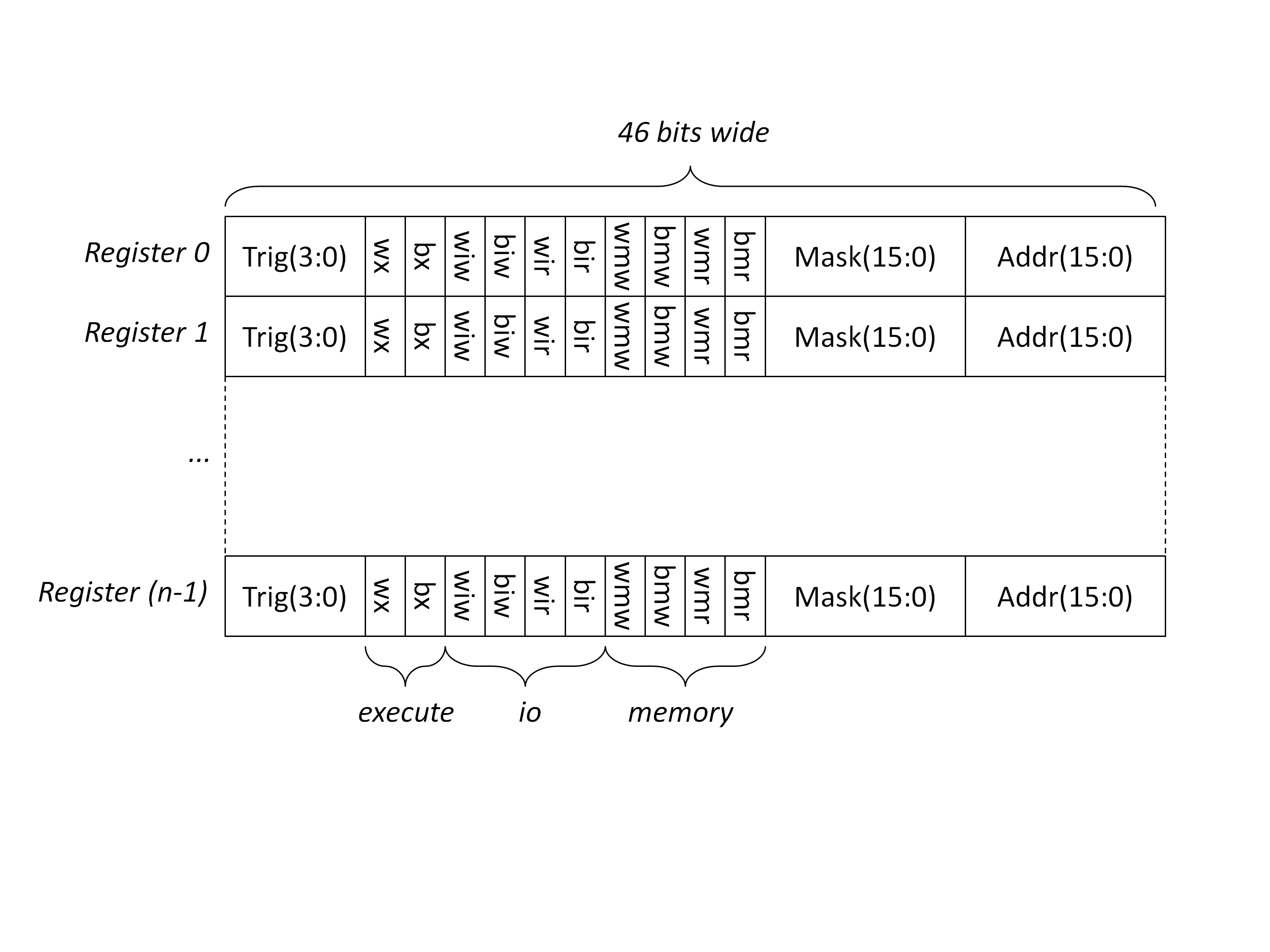
The number of entries in the breakpoint register 8 for the 6502 and 6809, and 4 for the Z80, as the Z80 processor core is larger, so there is less space in the FPGA. Each entry in the breakpoint register is 46 bits wide. So for the 6502, the size of the register is 46 x 8 = 368 bits.
To load the breakpoint register, data is shifted in one bit at a time by making multiple calls to the CMD_BRKPT_LOAD command (with the data bit value to be loaded in command bit zero). Each time the command is used, the register is shifted write one bit, and the data bit is places in the most significant bit. This means the order of the bits to be sent is bit 0 first and bit 367 last.
The Address/Dout register is used by commands that read or write host memory when the emulator is in command mode
This is a 24 bit register, where:
- bits 23..8 are the address (for reads and writes)
- bits 7..0 are the data (for writes only, for reads the data is accessed via the multiplexer, see below)
To load the Address/Dout register, data is shifted in one bit at a time by making multiple calls to the CMD_LOAD_MEM command (with the data bit value to be loaded in command bit zero). Each time the command is used, the register is shifted write one bit, and the data bit is places in the most significant bit. This means the order of the bits to be sent is bit 0 first and bit 23 last.
State from the bus monitor hardware can be read by via an 8-bit wide 48-to-1 multiplexer. The select input is set by writing a value (0 to 47) to Port D, and the 8-bit value can then be read back from Port E.
| Select | Value |
|---|---|
| 0 | Latched instruction address (7:0) |
| 1 | Latched instruction address (15:8) |
| 2 | Latched data bus value |
| 3 | Current cycle count (23..16) |
| 4 | Current cycle count (7..0) |
| 5 | Current cycle count (15..8) |
| 6 | Event instruction address (7:0) |
| 7 | Event instruction address (15:8) |
| 8 | Event address (7:0) |
| 9 | Event address (15:8) |
| 10 | Event data bus value |
| 11 | Event status |
| 12 | Event cycle count (7:0) |
| 13 | Event cycle count (15:8) |
| 14 | Event cycle count (23:16) |
| 15 | unused |
| 16..47 | processor registers (see below) |
Code that is specific to a target processor is factored out into separate files. This is really just two things:
- An opcode disassembler
- A register formatter
Opcode Disassembler
This reads the opcode from host memory and formats it for printing.
The prototype for this is:
unsigned int disassemble(unsigned int addr);
The return value is the address of the next opcode.
For the 6502, the implementation is:
For the Z80, the implementation is:
For the 6809, the implementation is:
Register formatter
This reads the register data via the wide multiplexer described above.
The prototype for this is:
void doCmdRegs(char *params);
i.e. is entire implementation of the regs command.
For the 6502, the implementation is:
For the Z80, the implementation is:
For the 6809, the implementation is: