updated 21 April 2022
This is a simple project in Arduino that uses the breadboard, the Arduino UNO Board, the 7-Segment Display and basic programming. Take note, there are several ways to do this same project but we'll focus on one.
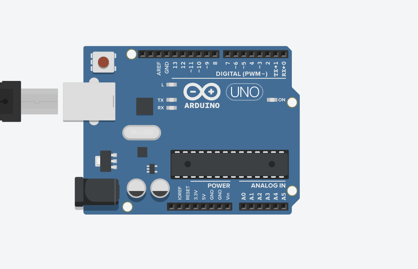
The Arduino UNO Board is the basic board for beginners doing projects in Arduino.
As from the previous project, without a microcontroller, your only control is through an external switch. And you are just limited to that.
The microcontroller will enable you to program electronic components so that you can build digital devices that you want to build.

The digital pins are the very first to be encountered because they can be used by components in several ways. They will be connected to the terminals of electronic components. There are 14 Digital Pins in Arduino UNO Board.

The GND is the floating ground to complete the circuit. Remember, in an electrical setup the earth ground is used extensively. In electronics, it's the convenience to use a floating ground.
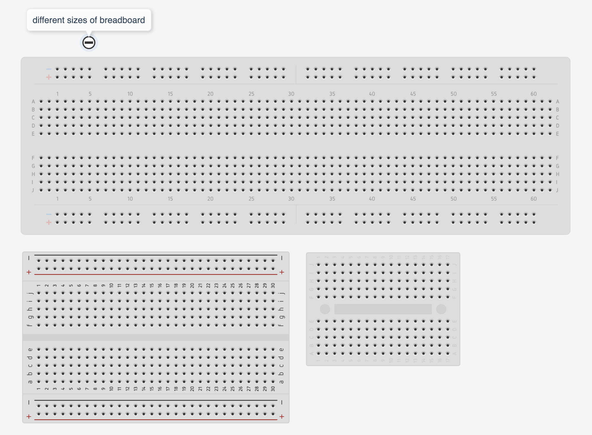
The breadboard is your convenience for you to simply put things in place. Plus, it provides connections either horizontally or vertically for further ease. Because of this, you avoid overlapping wires: the metal strip at the bottom provides the connection.

To not complicate things, we just use one 7-Segment Display for the output. Remember, computer monitors' concept of display is the same: the dot-and-no-dot pattern to create a display, whether an image or letter or numbers. You can do the same thing by using LEDs to serve as pixels.
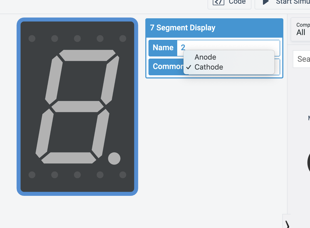
But here in our project, we want to use the 7-Segment Display as an upgrade from the basic LEDs. It's called 7-Segment Display because there are seven segments of LEDs, forming the number 8 unlighted.

The 7-Segment Display will either use cathode or
anode. Make sure you got it right. It depends on
your circuit design.
There are just two default functions in Arduino:
void setup and void loop.
void setup is where you tell the Arduino board about
the common setup just like whether a digital pin will
be used as output or input.
void loop is where the Arduino board executes
all the commands you put there just like
digitalWrite whether high or low. HIGH means
there is a voltage supplied just like turning
it on through an external switch and LOW means
there is no voltage supplied or there is but is
too low. Voltage that is not
sufficient will still be just like no voltage at all.
Using the TinkerCAD, here are the steps to create the project:
-
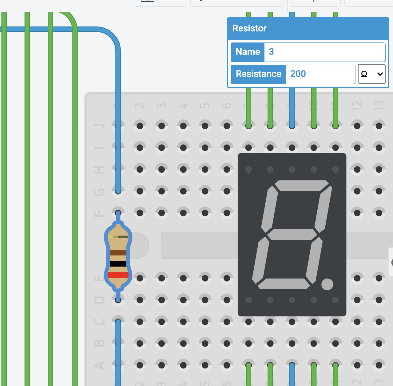
Make sure that you change the 7-Segment Display common terminal to
cathode.
-
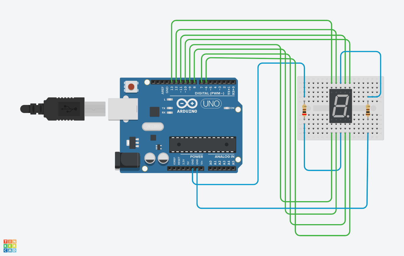
Follow the proper wiring:
Arduino Pin Segment Pin 13 G 12 F 11 A 10 B 9 E 8 D 7 C 6 DP -
Close the circuit by the GND. Use a resistor that is exactly 200 ohms (left resistor when facing the screen) and 100 ohms for the other one. left:
 right:

-
Copy paste the program below:
unsigned const int A = 13;
unsigned const int B = 12;
unsigned const int C = 11;
unsigned const int D = 10;
unsigned const int E = 9;
unsigned const int F = 8;
unsigned const int G = 7;
unsigned const int H = 6;


void setup(void)
{
  pinMode(A, OUTPUT);
  pinMode(B, OUTPUT);
  pinMode(C, OUTPUT);
  pinMode(D, OUTPUT);
  pinMode(E, OUTPUT);
  pinMode(F, OUTPUT);
  pinMode(G, OUTPUT);
  pinMode(H, OUTPUT);
}

//functions to display
//the numbers
void displayZero(void) {
  digitalWrite(A, LOW);
  digitalWrite(B, HIGH);
  digitalWrite(C, HIGH);
  digitalWrite(D, HIGH);
  digitalWrite(E, HIGH);
  digitalWrite(F, HIGH);
  digitalWrite(G, HIGH);
  digitalWrite(H, LOW);
}

void displayOne(void) {
  digitalWrite(A, LOW);
  digitalWrite(B, LOW);
  digitalWrite(C, LOW);
  digitalWrite(D, HIGH);
  digitalWrite(E, LOW);
  digitalWrite(F, LOW);
  digitalWrite(G, HIGH);
  digitalWrite(H, LOW);
}

void displayTwo(void) {
  digitalWrite(A, HIGH);
  digitalWrite(B, LOW);
  digitalWrite(C, HIGH);
  digitalWrite(D, HIGH);
  digitalWrite(E, HIGH);
  digitalWrite(F, HIGH);
  digitalWrite(G, LOW);
  digitalWrite(H, LOW);
}

void displayThree(void) {
  digitalWrite(A, HIGH);
  digitalWrite(B, LOW);
  digitalWrite(C, HIGH);
  digitalWrite(D, HIGH);
  digitalWrite(E, LOW);
  digitalWrite(F, HIGH);
  digitalWrite(G, HIGH);
  digitalWrite(H, LOW);
}

void displayFour(void) {
  digitalWrite(A, HIGH);
  digitalWrite(B, HIGH);
  digitalWrite(C, LOW);
  digitalWrite(D, HIGH);
  digitalWrite(E, LOW);
  digitalWrite(F, LOW);
  digitalWrite(G, HIGH);
  digitalWrite(H, LOW);
}

void displayFive(void) {
  digitalWrite(A, HIGH);
  digitalWrite(B, HIGH);
  digitalWrite(C, HIGH);
  digitalWrite(D, LOW);
  digitalWrite(E, LOW);
  digitalWrite(F, HIGH);
  digitalWrite(G, HIGH);
  digitalWrite(H, LOW);
}

void displaySix(void) {
  digitalWrite(A, HIGH);
  digitalWrite(B, HIGH);
  digitalWrite(C, HIGH);
  digitalWrite(D, LOW);
  digitalWrite(E, HIGH);
  digitalWrite(F, HIGH);
  digitalWrite(G, HIGH);
  digitalWrite(H, LOW);
}

void displaySeven(void) {
  digitalWrite(A, LOW);
  digitalWrite(B, LOW);
  digitalWrite(C, HIGH);
  digitalWrite(D, HIGH);
  digitalWrite(E, LOW);
  digitalWrite(F, LOW);
  digitalWrite(G, HIGH);
  digitalWrite(H, LOW);
}

void displayEight(void) {
  digitalWrite(A, HIGH);
  digitalWrite(B, HIGH);
  digitalWrite(C, HIGH);
  digitalWrite(D, HIGH);
  digitalWrite(E, HIGH);
  digitalWrite(F, HIGH);
  digitalWrite(G, HIGH);
  digitalWrite(H, LOW);
}

void displayNine(void) {
  digitalWrite(A, HIGH);
  digitalWrite(B, HIGH);
  digitalWrite(C, HIGH);
  digitalWrite(D, HIGH);
  digitalWrite(E, LOW);
  digitalWrite(F, HIGH);
  digitalWrite(G, HIGH);
  digitalWrite(H, LOW);
}

//execute the codes
//by invoking the functions
void loop(void)
{

  displayNine();
  delay(1000);

  displayEight();
  delay(1000);

  displaySeven();
  delay(1000);

  displaySix();
  delay(1000);

  displayFive();
  delay(1000);

  displayFour();
  delay(1000);

  displayThree();
  delay(1000);

  displayTwo();
  delay(1000);

  displayOne();
  delay(1000);

  displayZero();
  delay(1000);

}
The code will simply have the countdown but the individual function for a certain number can be used several times for your own version. Simply invoke the function inside the
void loop. -
Of course, simulate the program!
-
Final Version: add a border using LEDs with your own pattern of blinking or group of LEDs of your own style. Make the
7-Segment Displaycomponent display letters to form words that have significance to you. There should be at least 2 words presented and another two groups of numbers like your birth date, year you were born, significant date in your life, lucky numbers for you, etc. Explain the significance by using comments.

Finally, the actual project is here: