A simulink/matlab control study of a Solar Panel that is designed to rotate towards the sun's exposure This is an experiment based on matlab simulink tutorials, the data used can be founded on their website
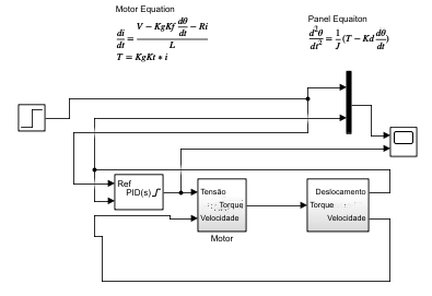
The system uses a voltage input to control the position of the Panel based on the error feedback provided by the following system(in block diagram):
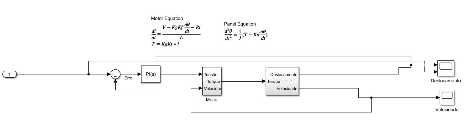
It was used a PI controller because that was no need to incorporate the derivative part of the equation, being that we are supposed to be able to pinpoint the sun's position at every instant and we´re not considerating abrupt changes such as cloud appearences.
The system is based in the motor and the panel rotation. First, the motor is described by the following equation and block diagram:
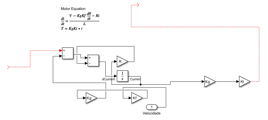
As you can see, the output of this subsystem is the Torque, which has been fed with the panel current angle velocity and the input voltage.
As for the Panel rotation, here we have the equation on which he is rotating and his subsystem's block diagram

As you can see, the subsystem feeds our final output(position) to the scope and for the system feedback, and the velocity feedback for the motor subsystem.
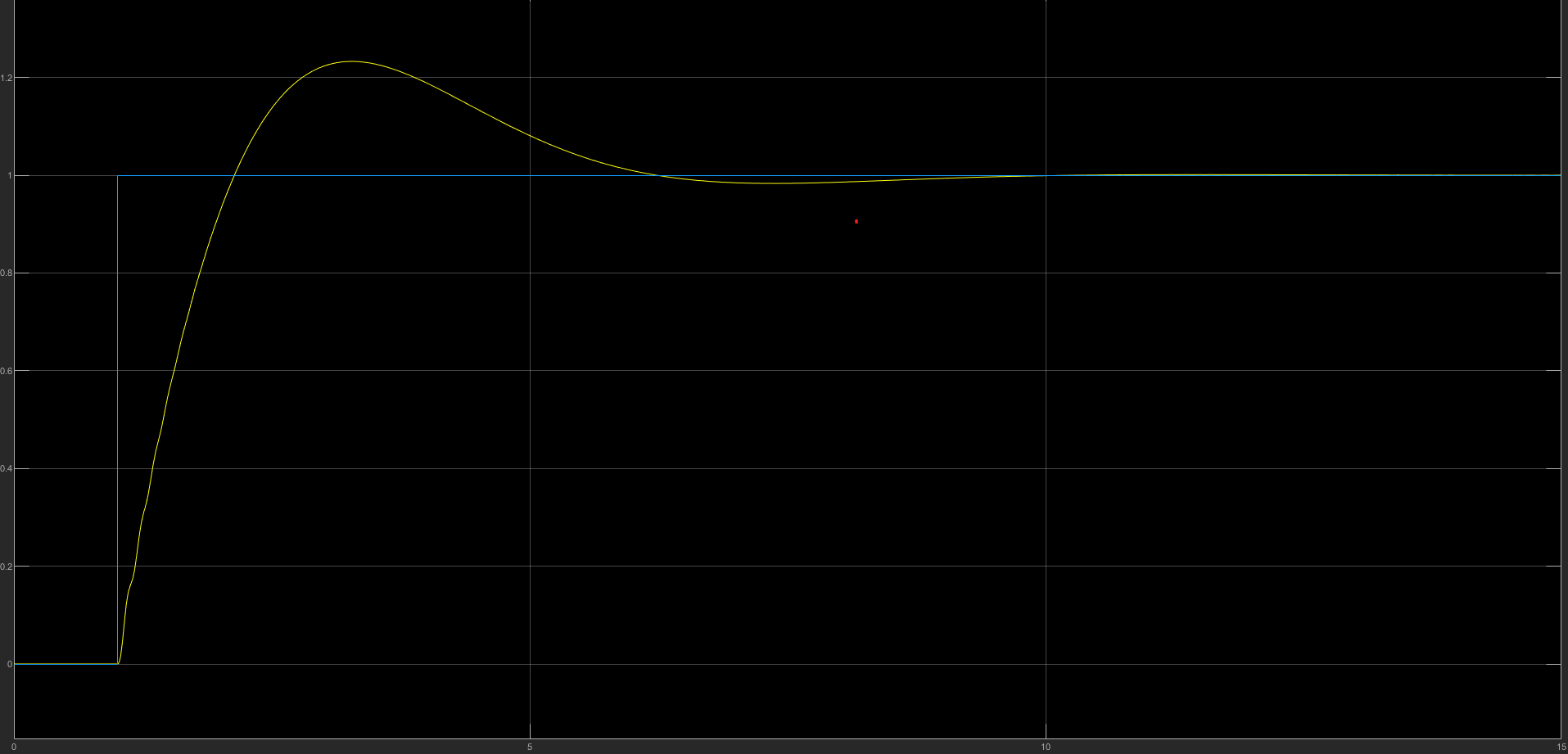
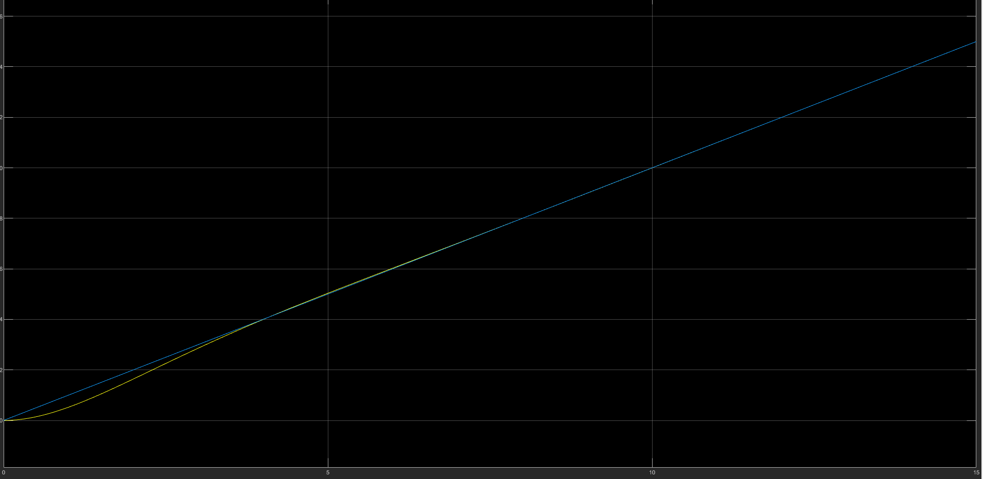
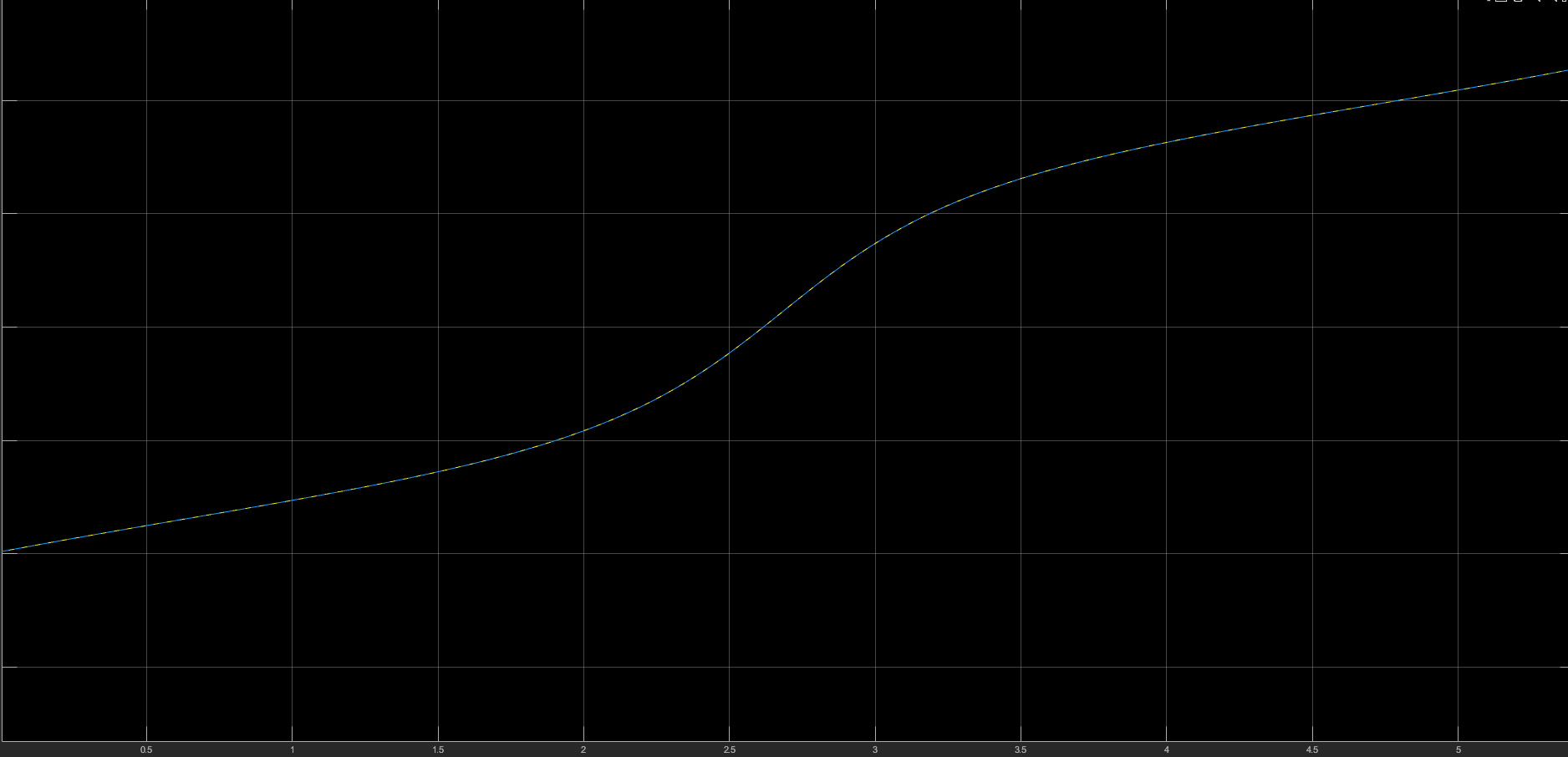
Some results with different inputs:
Step:
Ramp:
Sun's Position:
After the initial results a study was made to proper tune the PID controller, in fact, it was used a I-PD controller, tuned by the Sokegestad rules, all in which will be displayed above. The tuning is made based on the transfer function time constants and gains. All the math is displayed Above:
- Finding the transfer function using the following differential equations

with the parameters that were explicit in the params file, we can assume that L/R is aproximate to zero, than, we can use this transfer function:

- Provided with the approximate transfer function, we’re able to easily see that it represents a first order system with a integrator. Using Skogestad SIMC rules for first order systems with a integrator in series and its conversion to ideal I-PD we have:

In this section we'll observe the differences in the process with the current presented setting and the previous step signal entry results First, let's look into the "new" block model with the I-PD controller and the display of the voltage in the major scope
Now, we'll see the results with the step entry:

However, even with the new efficient results removing the overshoot, we must use a limit to our voltage input to a -24 to 24, using a saturation that is provided whithin the I-PD block, resulting in the following wind-up effect:

To ensure that out system is fighting this effect, we'll use the anti-wind up method of back calculation with the kb = 0.3, this provide the following results for the same -24 to 24 voltage input saturation
