| Part name | Quantity | Remarks | Photo |
|---|---|---|---|
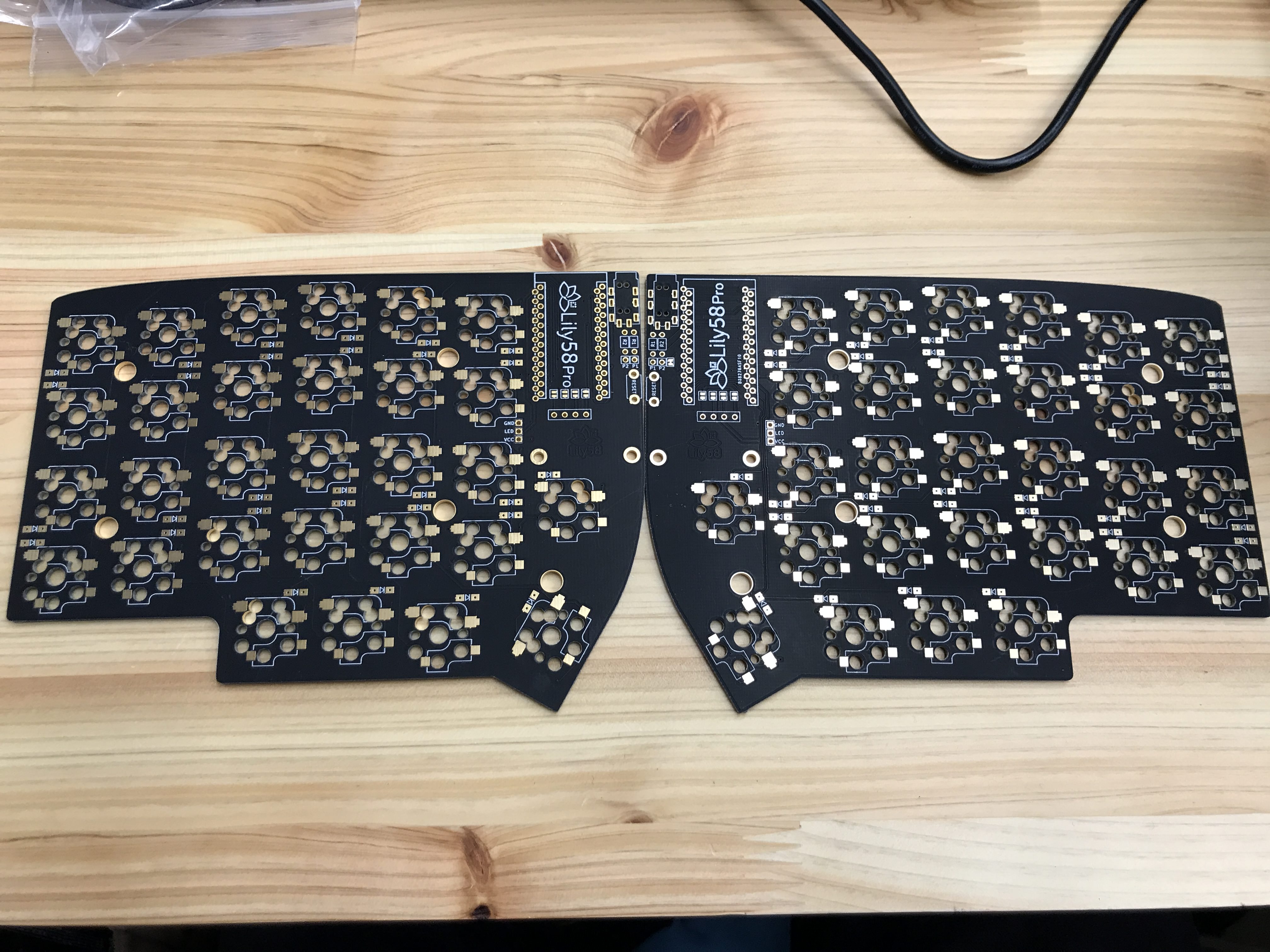
| Lily 58 PCB | 2 pieces | ||
| Lily 58 case | 1 set (4 pieces) | 2 solid panels, 2 with holes for switches | |
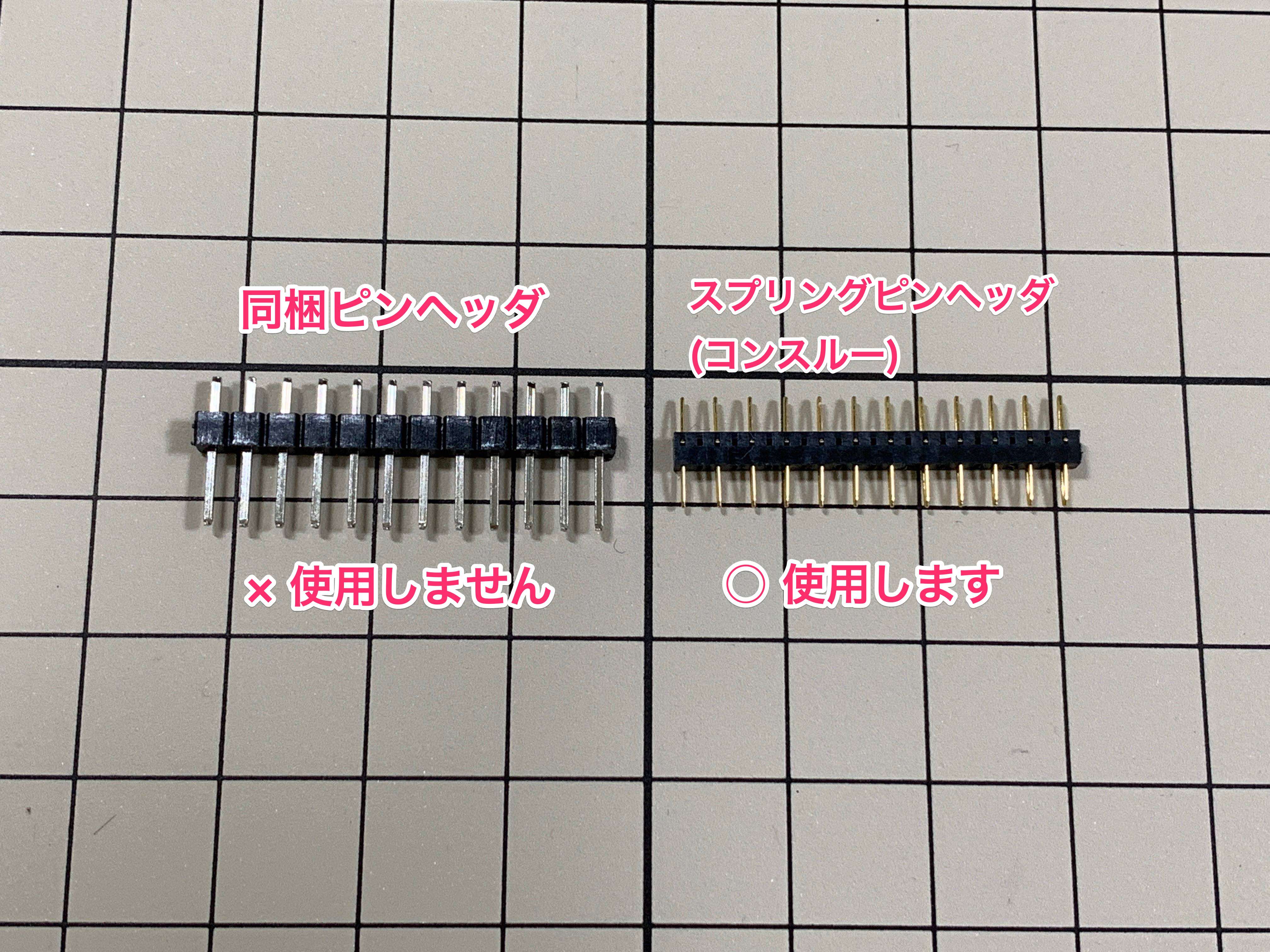
| ProMicro | 2 pieces | Optionally, use a spring pin header (con-through) to reduce soldering and avoid damage to the fragile ProMicro board. (The recommended con-through part is included in the kit sold at YushaKobo.) | |
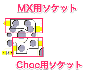
| Key switch (Cherry MX, Kailh choc) | 58 pieces | MX switch and choc switches use separate connectors | |
| Switch socket | 58 pieces | Necessary for key switch installation | |
| Diodes 1N4148W | 58 pieces | ||
| Key caps | 58 pieces | 1.5U caps, can also be 1U | |
| OLED module | 2 pieces | ||
| Tact switch | 2 pieces | Tactile reset switch | |
| TRRS jack | 2 pieces | ||
| M2 spacer | 10 pieces, 4 pieces | Choc: 4mm, MX: 7mm | |
| M2 screw | 28 pieces | ||
| TRRS cable | 1 cable | Cable for 3.5 mmaudio, also called AUX cable (4-pole cable recommended) | |
| Micro USB Cable | 1 pcs | Magnetic connector recommended due to the low durability of the ProMicro socket |
The Pro version has color variations, and the photos in this build guide are are of the black version, but the white verison is functionally identical. Depending on the color and release date, some parts may differ, but there is no difference in operation.
Note that the case of the black version has a scratch-resistant paint (solder resist) that can arrive with scratches from shipping and transportation. This is the nature of the product.
In addition, please be careful, as the case will be scratched if it hits or rubs a hard thing after assembly.
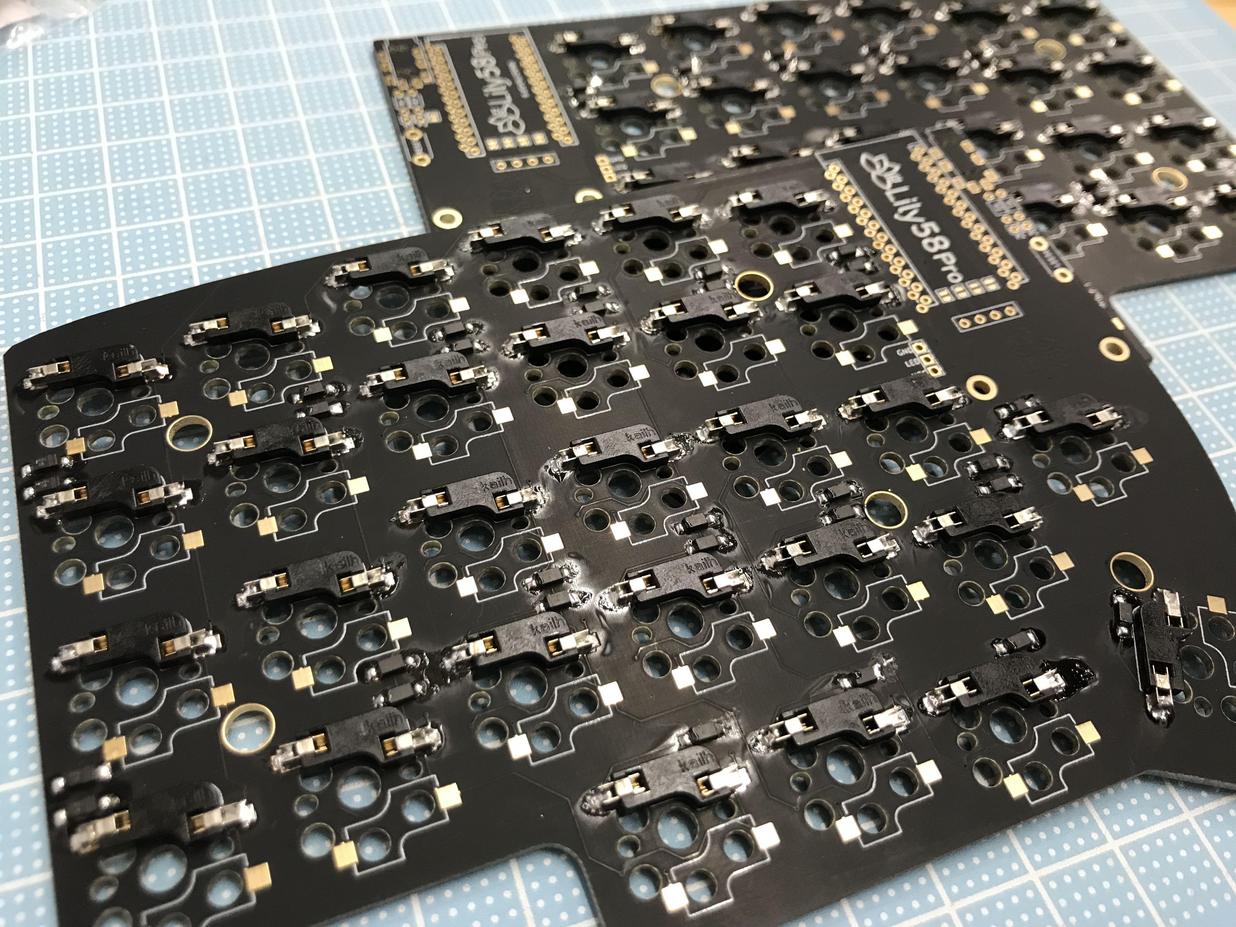
This substrate (PCB) is reversible. We will mount parts on each side.
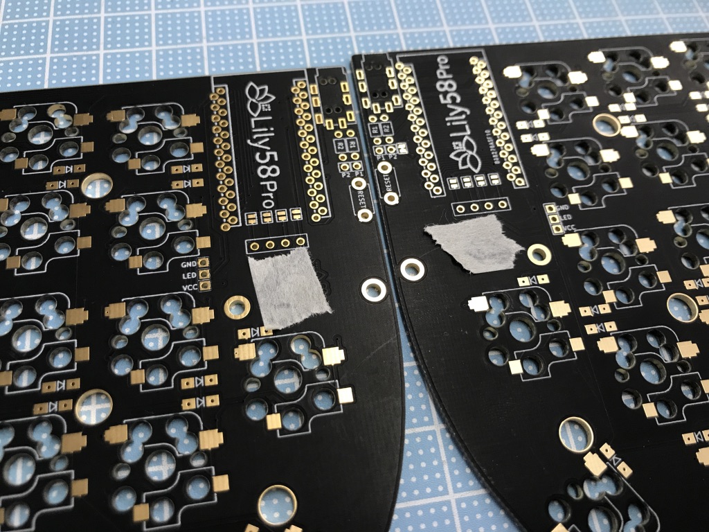
Mark the surface with masking tape to make it easy to keep track of the back and front of each board.
The diodes are supplied in a plastic tape reel. It's easy for the components to fly out when peeling back the tape, so open it slowly and carefully. (It's easier to work the diodes if you cautiously open the container onto a small plate.)
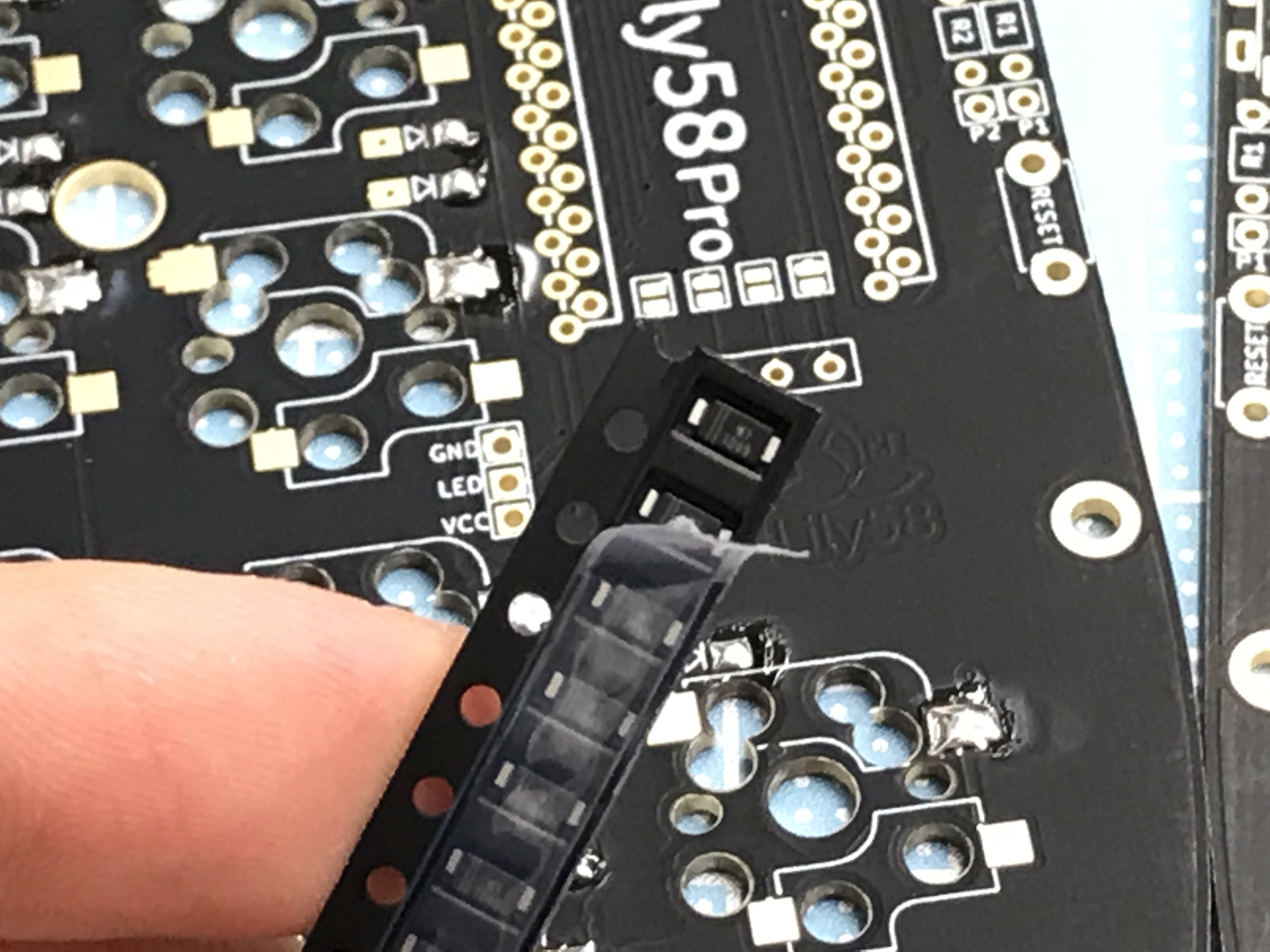
The diodes are mounted on the back side of the board.
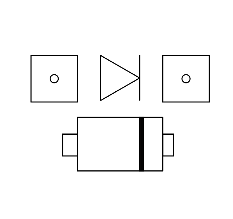
Solder with the diode wire always pointing in the direction of the arrow symbol drawn on the board (shown in the following figure). If the orientation is incorrect, the key will not respond.
Apply preliminary solder (melt a small amount on the substrate) on one pad of the PCB diode.
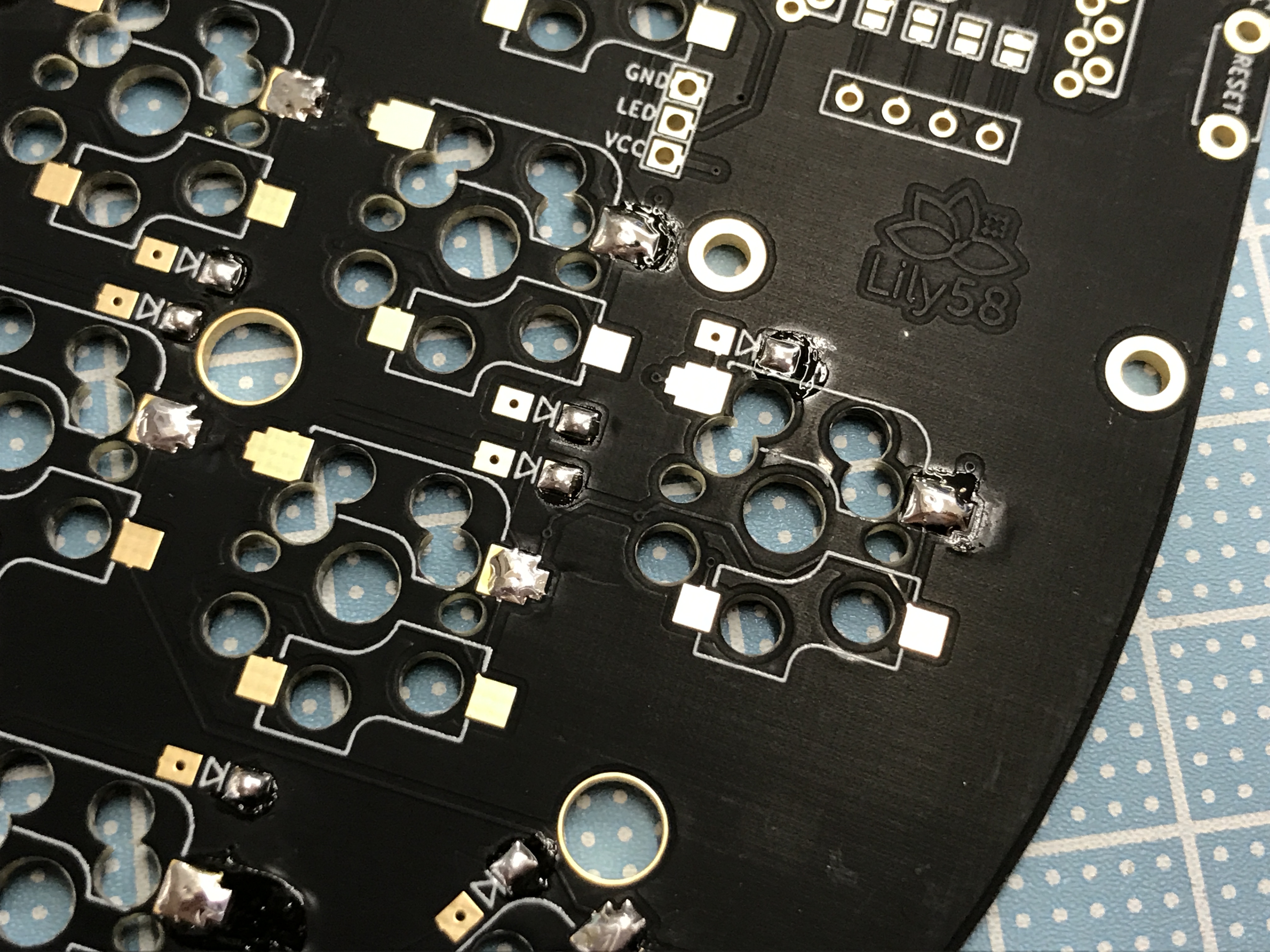
Then use tweezers to solder one side of the diode, using the pre-soldering to secure the diode.
 Then solder the remaining side.
When all diodes have been soldered, check for missing spots.
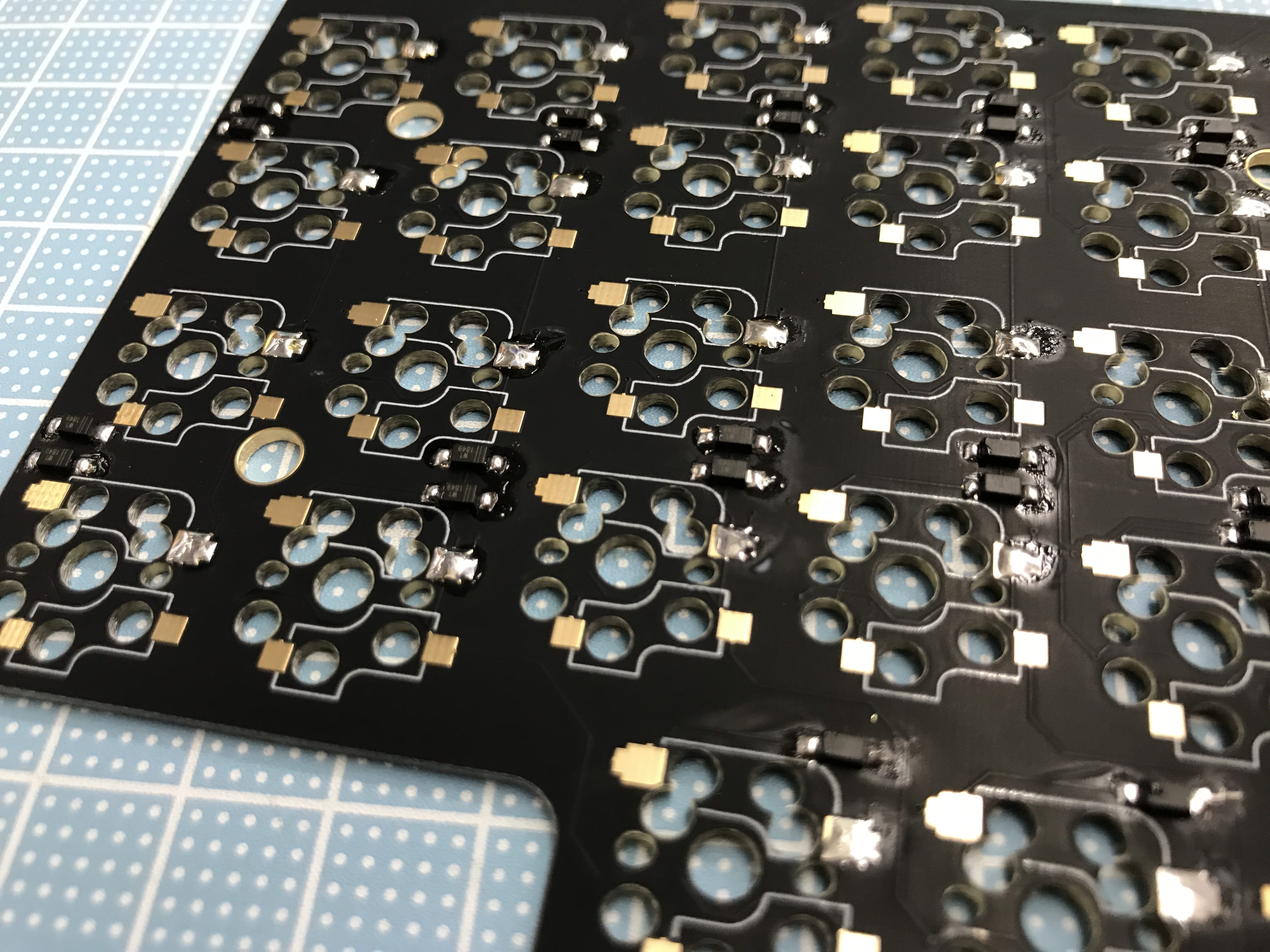
You can use a multimeter on the front side of the board to ensure that the solder connections are good and that the orientation of the diodes is correct.
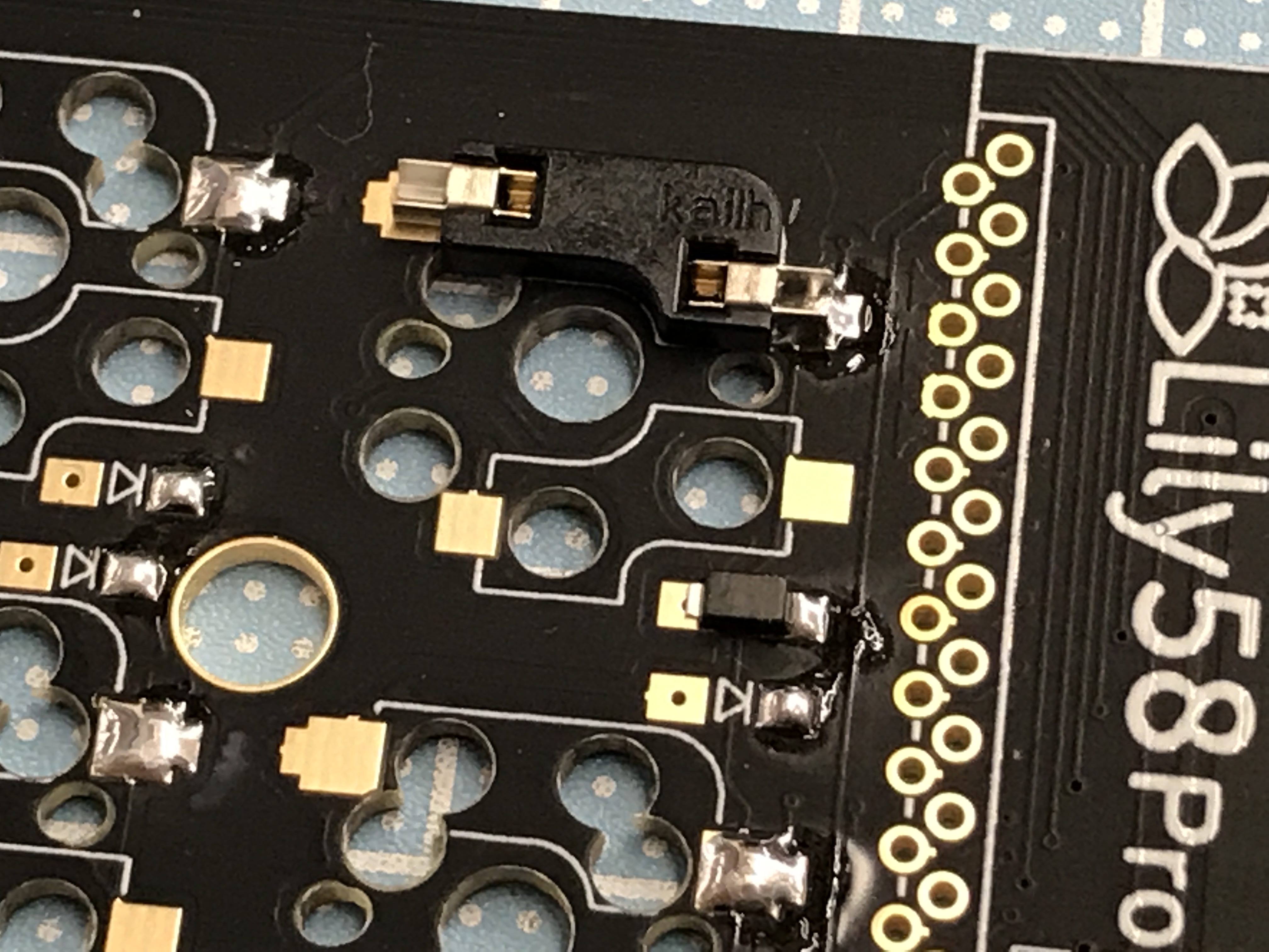
The sockets are mounted on the back side, the same side as the diodes.
Much like the approach used for the diodes above, begin by pre-soldering one side of the socket pad, place the component, and hold it in place with tweezers. (The sockets can also be held in place by hand, but please take extra care not to burn yourself.)
The image shows a soldered MX socket; please install Choc socket on the lower side.
For parts that require force, firmly solder both pads and check the final result for any looseness/wiggling.
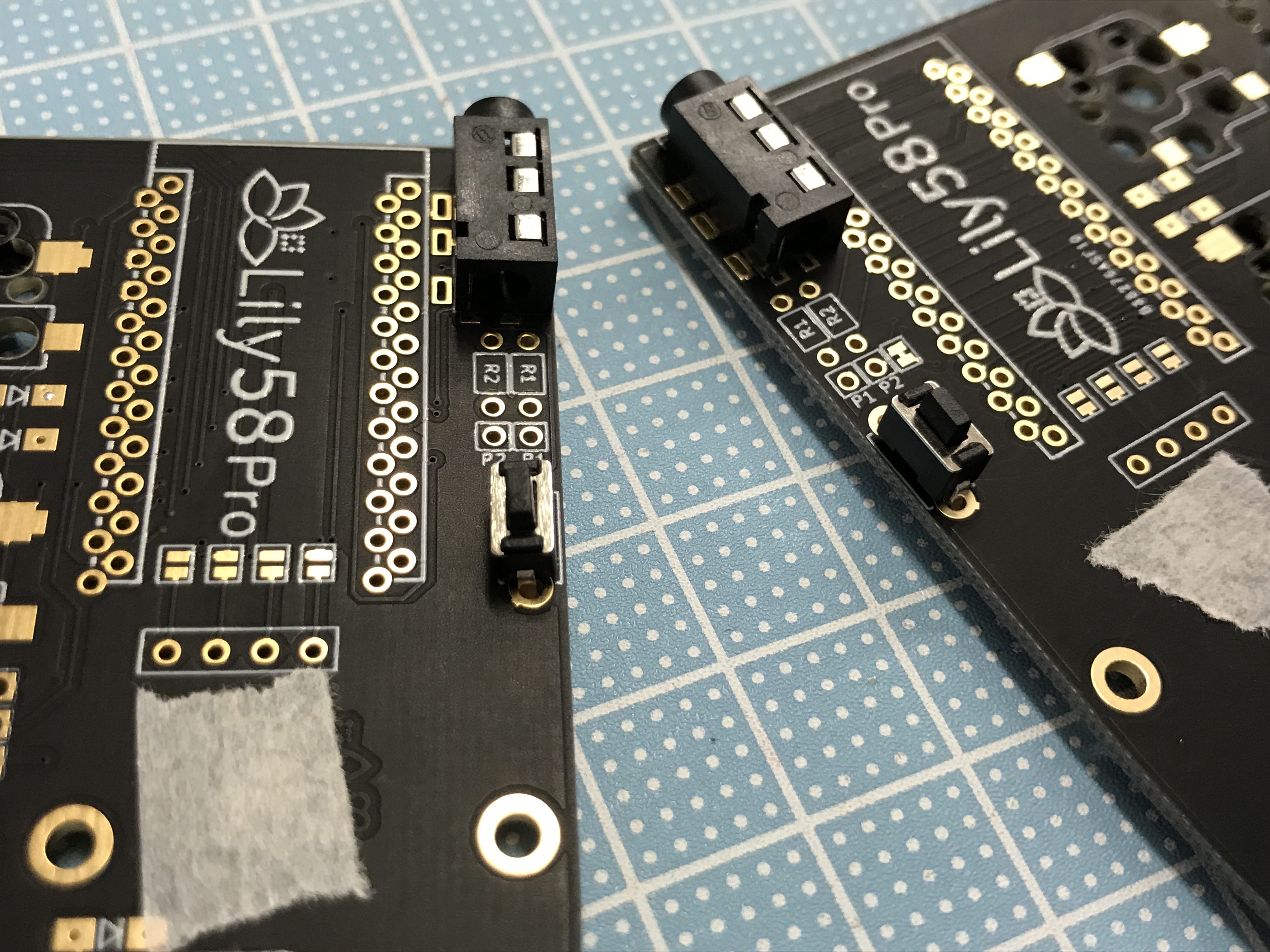
The TRRS jack and the reset switch are mounted on the front side (the one with the sticker on the mark).
Attach the parts and fix them temporarily with masking tape. Turn over the board and solder the pins, making sure that the TRRS jack and reset switch are in firm contact with the board.
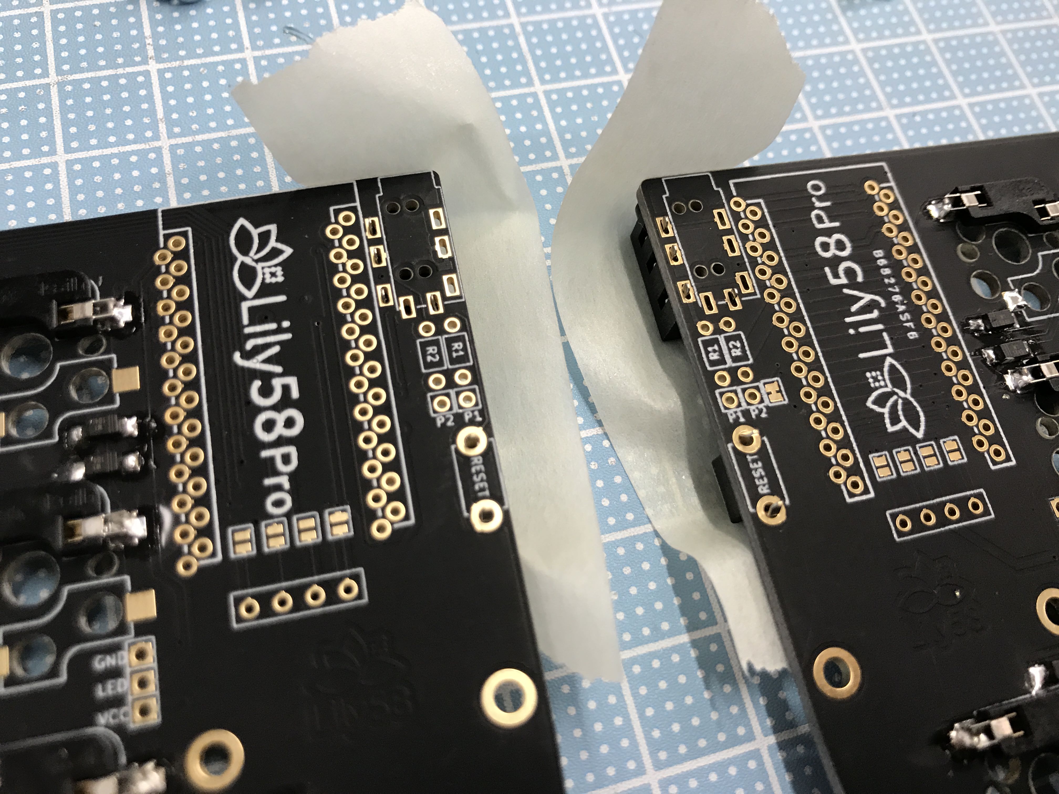
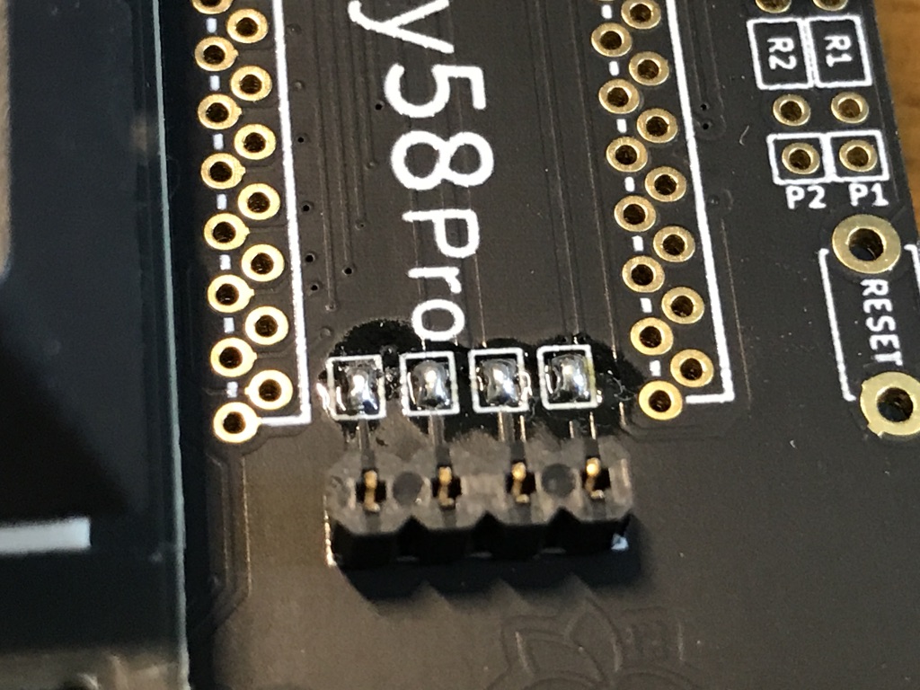
On the front side of the board, apply enough solder to bridge the four jumper terminals in the ProMicro section.
Attach the connector for the OLED, much like the TRRS jack above. Be careful to avoid adding a lot of solder, as it is easy for solder to flow into the connector.
Insert the OLED pin into the socket, attach the OLED module to it, and solder the four pins.
The pin header enclosed in the bag of ProMicro is not used. For kits purchased at YushaKobo, a spring pin header is included, so use that.
 When attaching with a spring pin header (con-through), solder it according to the method described in the Helix build guide and then attach it to the Lily 58 PCB. Helix build guide
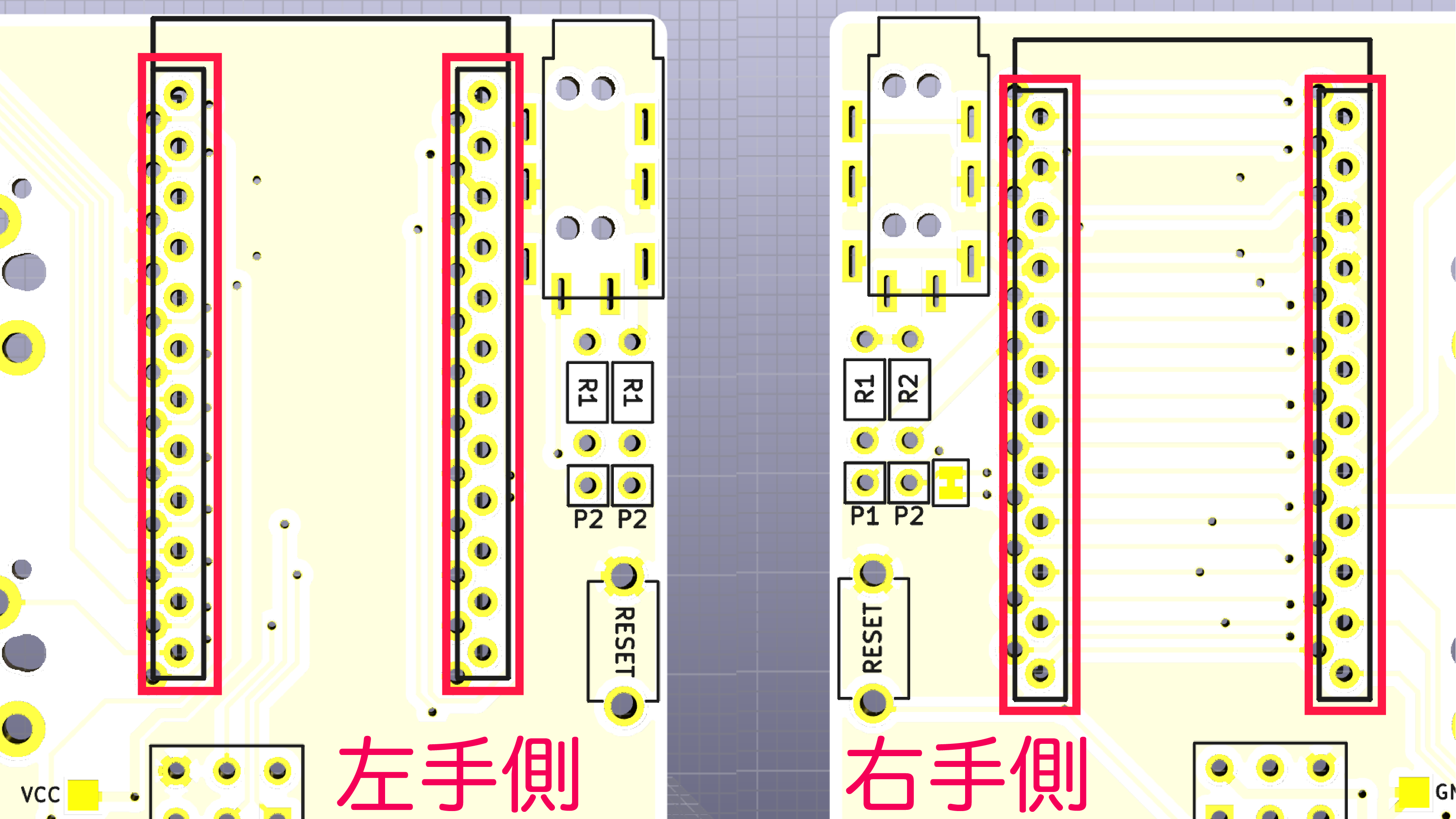
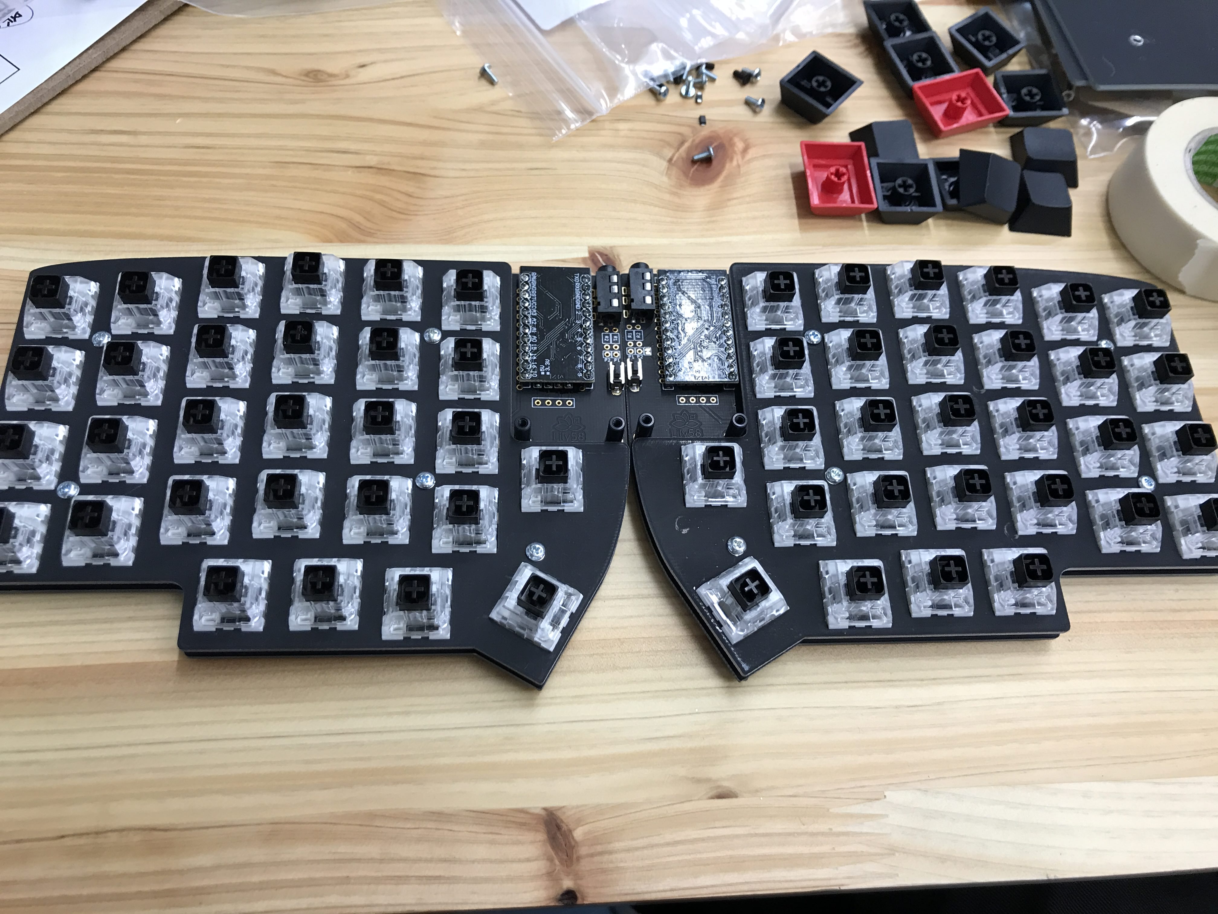
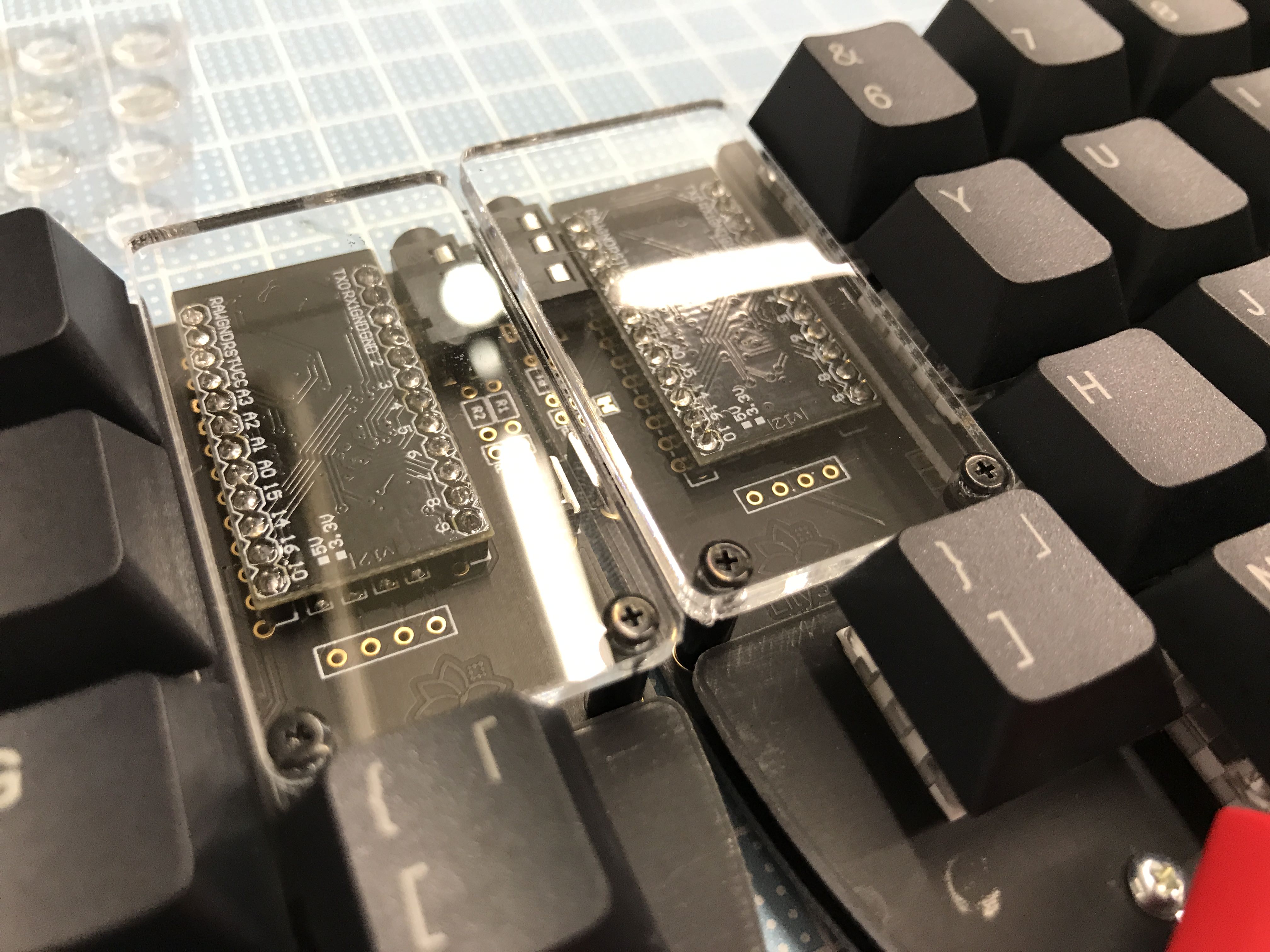
Note the outlined sets of holes in PCB, and insert the ProMicro into the outlined holes. Please be careful, as the connections are different for the right and left boards.
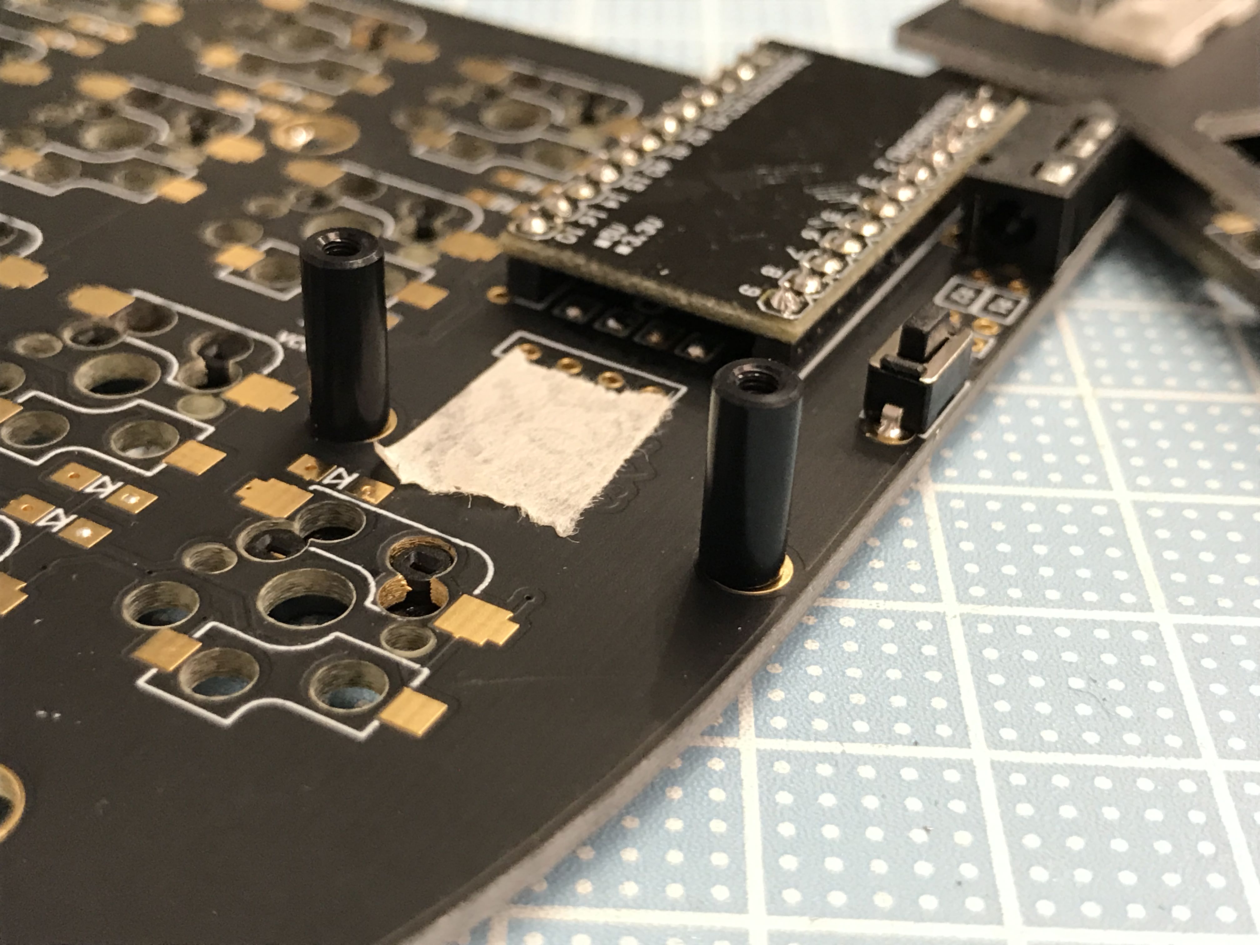
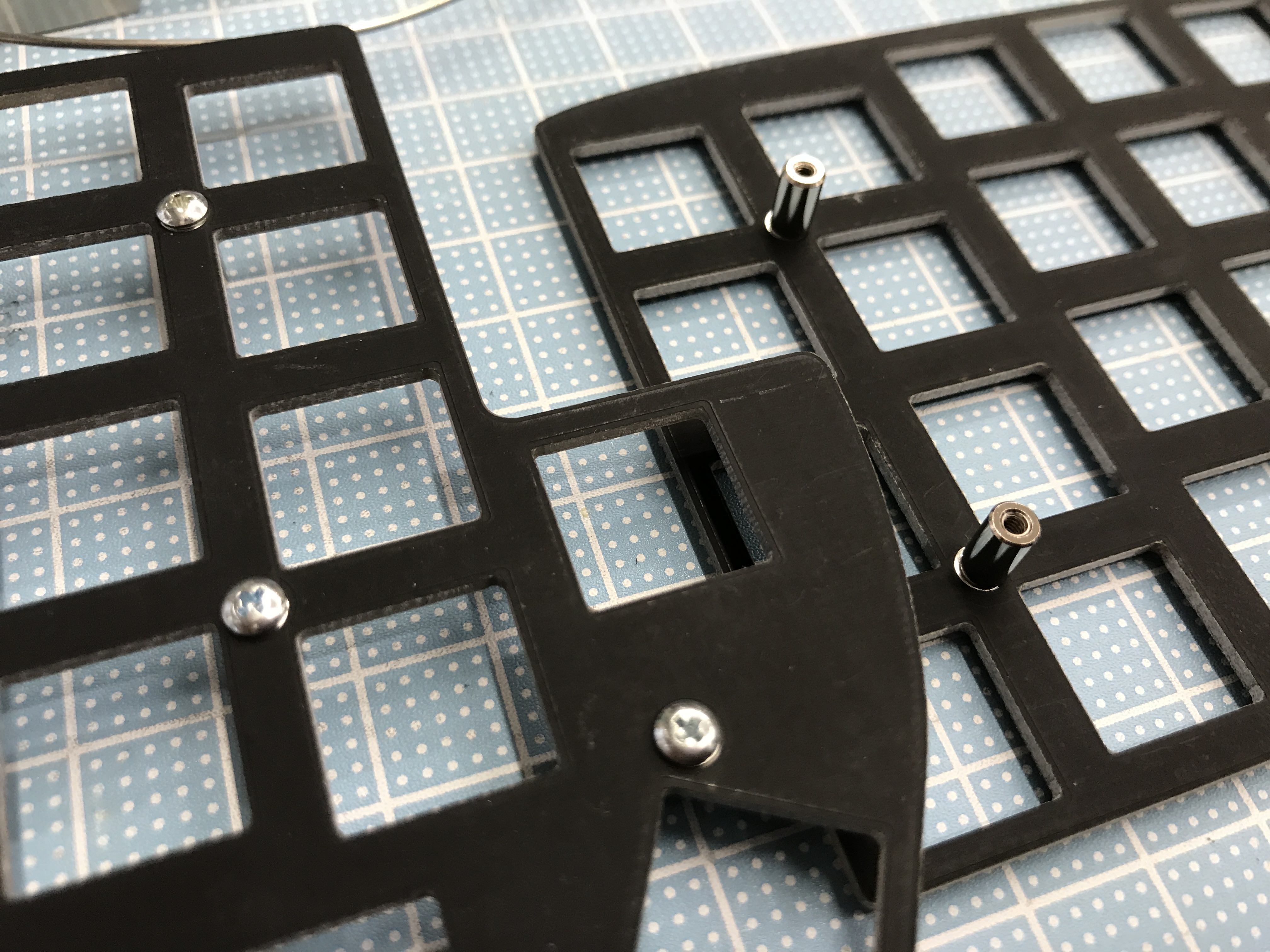
Attach four 10mm round spacers to the holes near ProMicro.
It's easy to insert a screw from the back of the board and attach the spacer from the top.
Peel off the masking tape used to identify the front and back of the board.
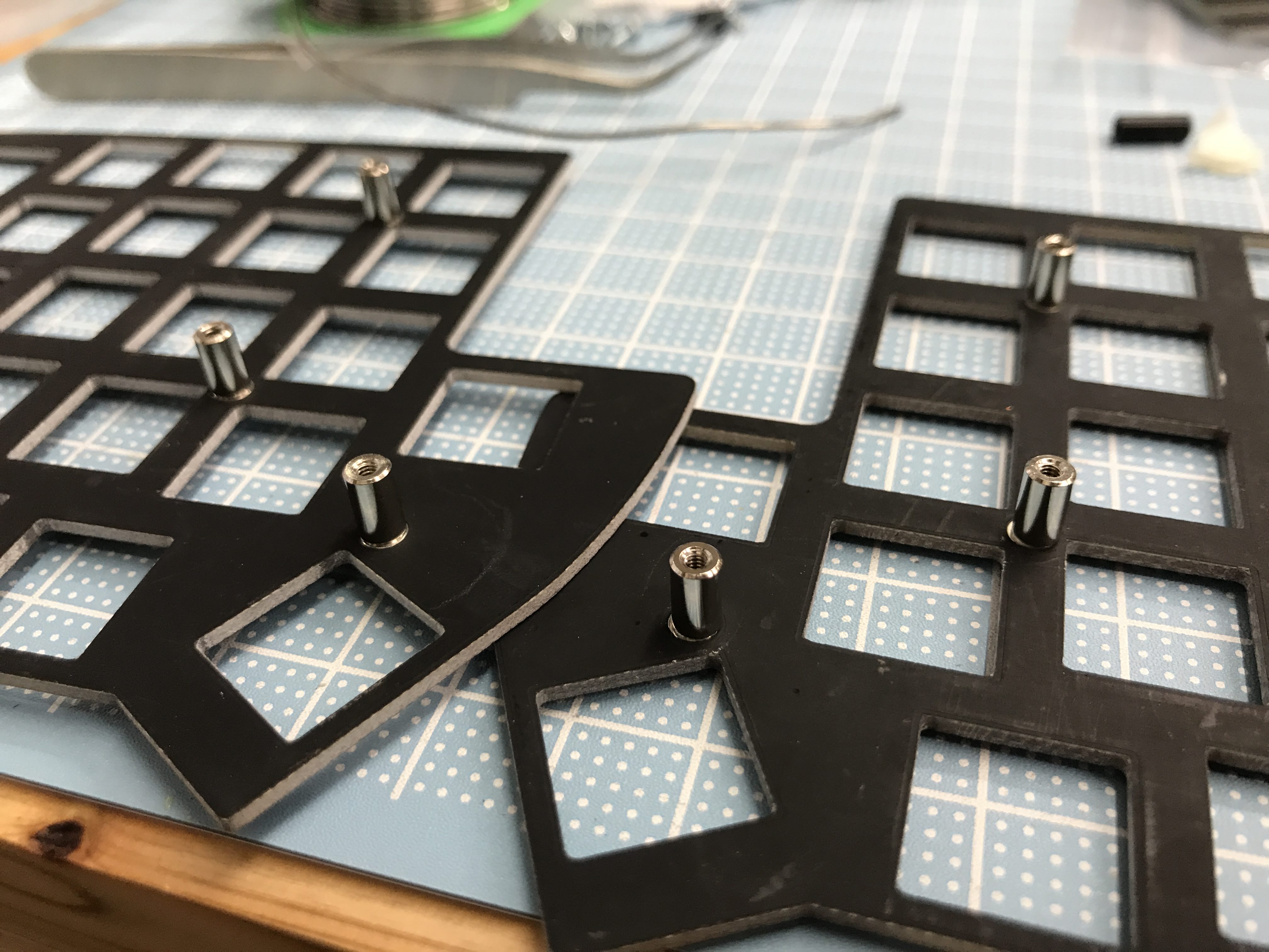
Attach the top plate spacers for alignment. (MX: 7mm Choc: 4mm)
Attach four key switches to the top plate. (In the case of Choc switches, starting with two switches in the plate may be easier.)
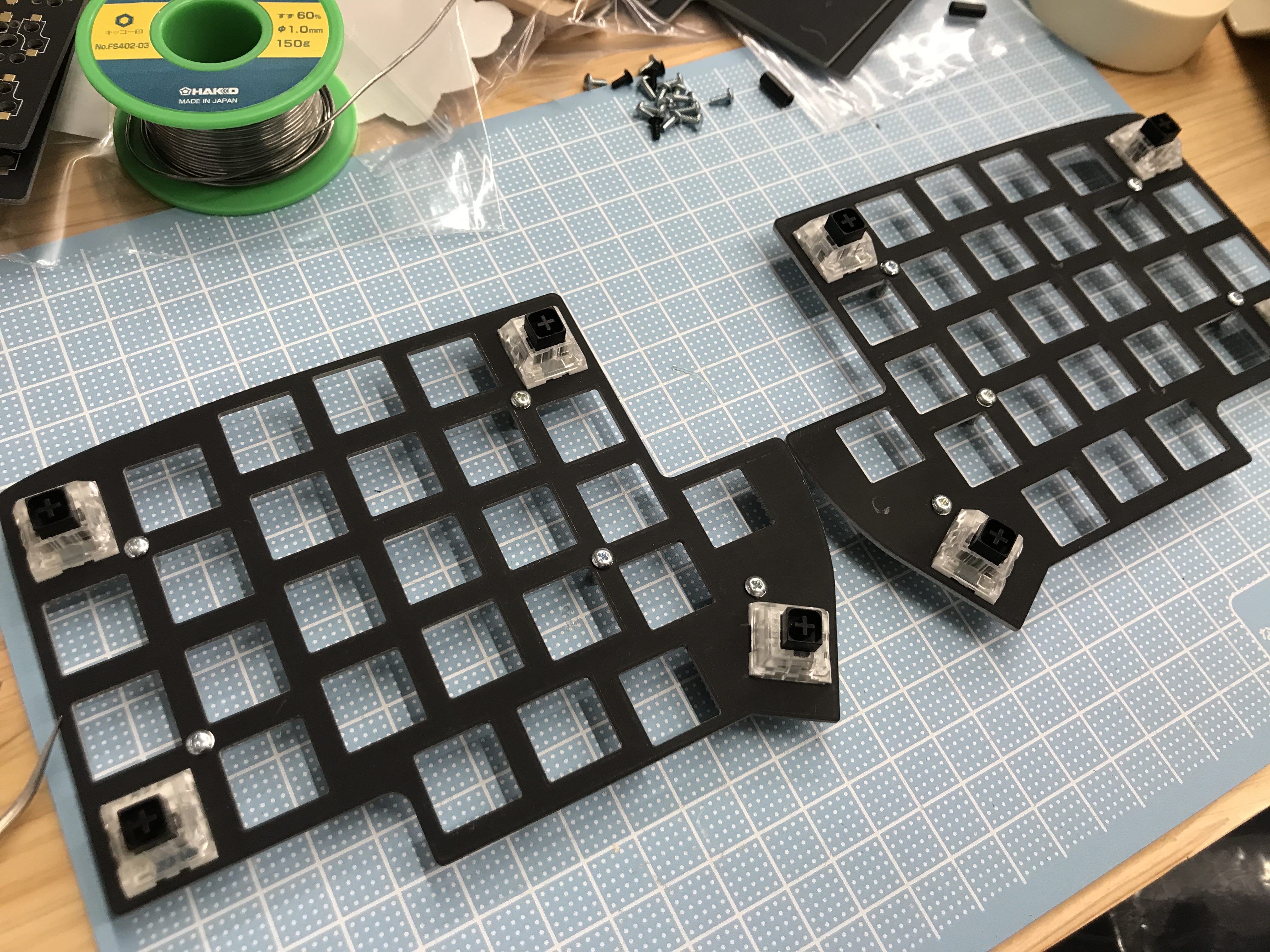
Insert the switch into the board for alignment, and line up the components.
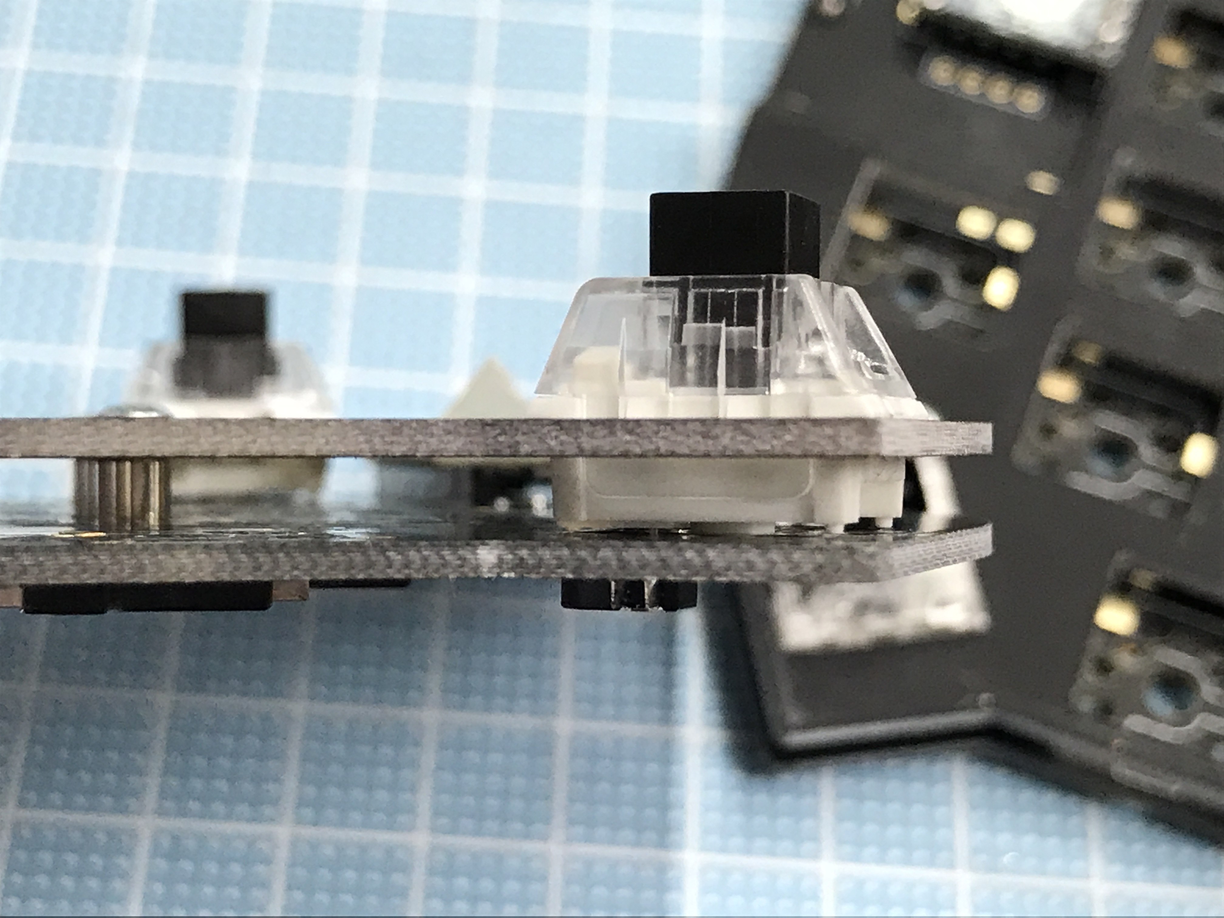
After confirming that there are no bends in the switch pins, you can attach it firmly by starting from the middle row and working outward.
Be careful: KailhBOX switches and Choc switches require some power for installation.
After mounting the plate, push the switches again to make sure that installation is complete.
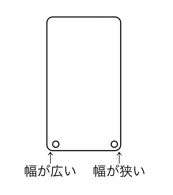
Peel off the protective plastic layer covering the acrylic, and attach the acrylic to the board. Mount with the wider side (labeled "幅が広い" here) outwards.
 .
.
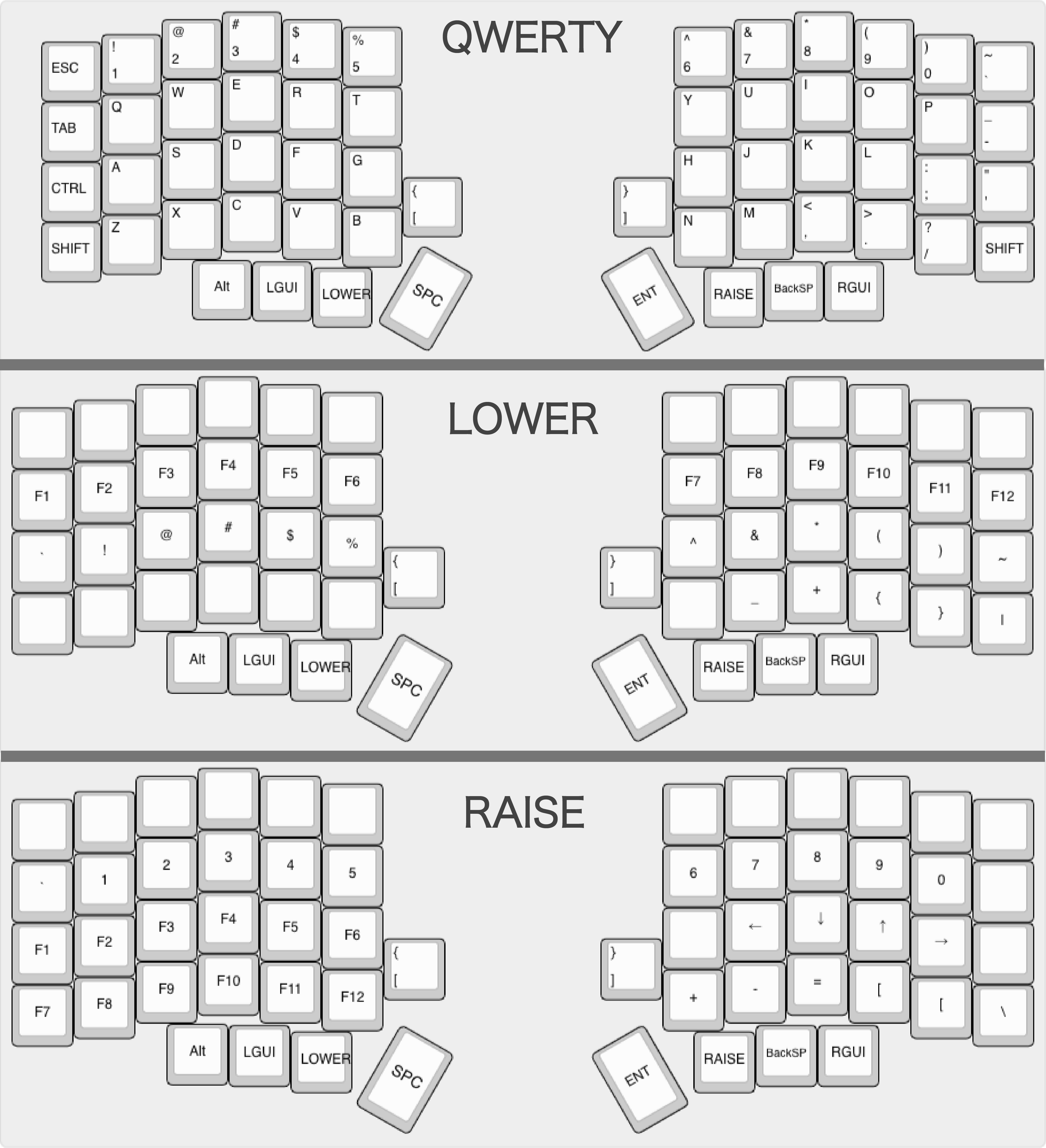
The board requires a keymap in order to function. This section assumes that you're familiar with keymaps and the use of the QMK tool. If not, please refer to the QMK "Getting Started" guide (Windows: MSYS2; Mac, Linux: avrdude)
The QMK Toolbox can be used to write non-customized keymaps via a GUI, avoiding the need to configure a local QMK environment. (For custom keymaps, it's recommended to build the full environment described above).
Execute the following in the qmk_firmware directory to write the default Lily58 keymap
sudo make lily58:default:avrdude
When Detecting USB port, reset your controller now ... is displayed, press the reset button on the keyboard to start writing.
Each half of the keyboard must be programmed separately using this approach.
The default keymap is laid out on the assumption that it will be used in the MacOS/US keyboard environment. Feel free to get creative and experiment with keymaps that match your preferences; consider changing to the JIS layout or adding a key to switch between English and Kana, for example.
The best of my own keyboard:
Connect the left and right sides with a TRRS cable, connect the MicroUSB cable to ProMicro on the left side (in the case of the default key map), and check if the key responds.
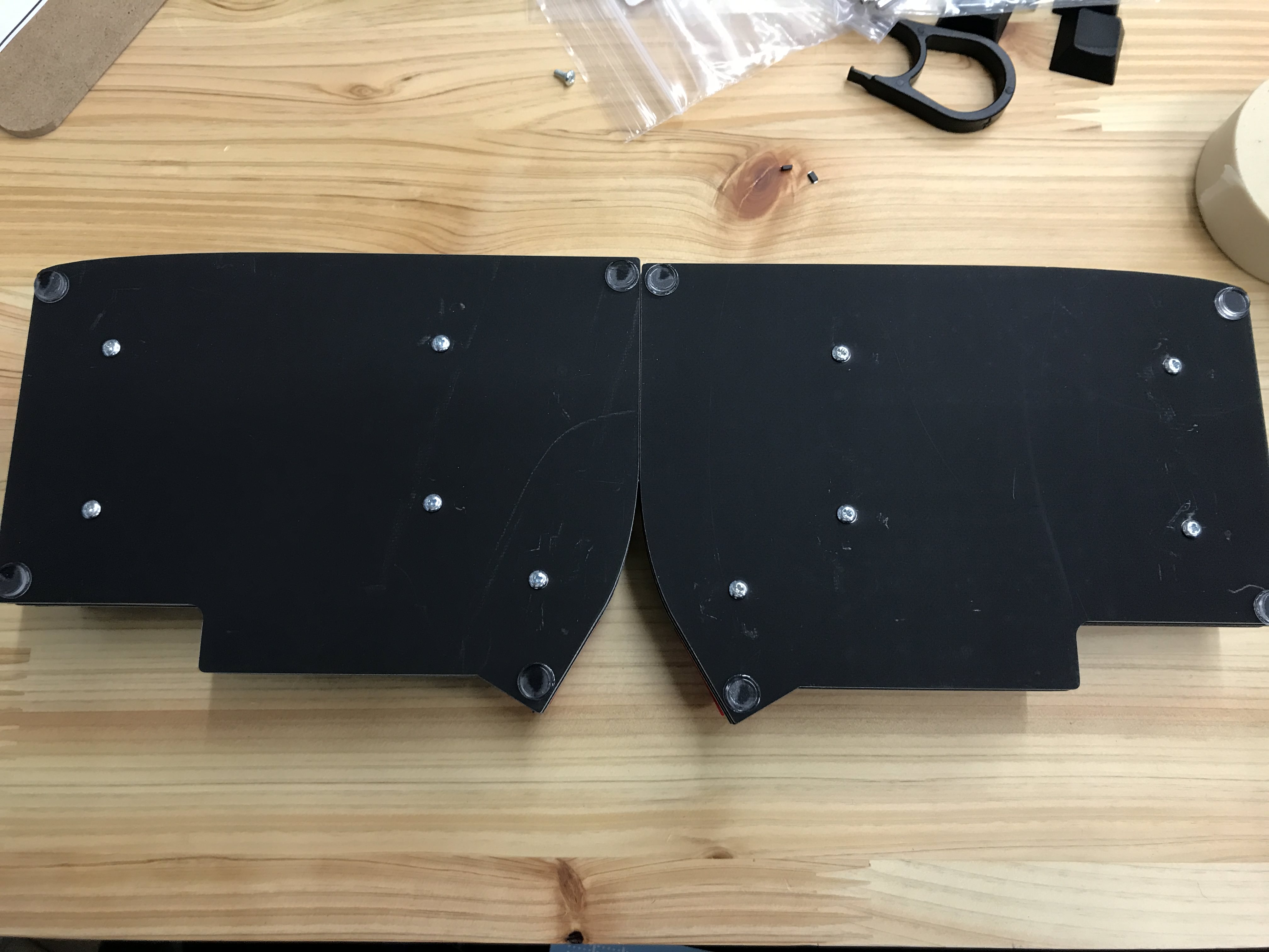
The build is completed by attaching the four rubber feet to the back of each board. Thank you for your hard work.
A. The ProMicro board may not be soldered and attached firmly. Check again, and re-solder and reinstall if necessary.
A. There may be a problem with the key switch's insertion, socket or diode soldering.
In the case of bad key switch insertion: After removing the key switch, make sure that the pins aren't bent, and then push it in again and install it.
In the case of badly attached socket: Re-solder the problem socket, or reflow and add solder if the joint is weak.
In the case of badly attached diode: Check the direction of the diode in question. If it is wrong, remove it and re-solder it. Additionally, if there isn't enough solder, please re-solder.
Since recognition of keyboard is recognized as JIS keyboard on OS, another symbol will be input when inputting with Lily 58 (treated as US keyboard). Please set Lily 58 as a US keyboard in the OS keyboard settings. After switching, switching to Japanese input becomes the switching key for the US keyboard, and it differs from the JIS keyboard, so please be careful (it can be customized with the key map etc.).
If you have any problems, please feel free to send a message to the "#Lily58" channel on Discord ("Self-Made Keyboards in Japan" (https://discordapp.com/invite/NM7XtDW)) or Twitter: @F_YUUCHI
This self-made keyboard use the QMK firmware, described above. The QMK firmware is highly customizable, and you can unlock a lot functionality simply by editing the key map.
When customizing a keymap, start by making a copy of the qmk_firmware/keyboards/lily58/keymaps/default folder and modifying that directory's internal keymap.c file.
Please refer to the official QMK documentation for the key codes and programming specifics.
After changing the key map,
sudo make lily58:(any folder name):avrdude
If you get an error, please double-check the board, connection and command.
If you use QMK Configurator, you can create an original keymap on the browser without editing the keymap.c file.
Load the downloaded JSON file into the QMK Toolbox and write it to the boards.