The aim of this project is to implement an automated grow box for mushrooms using Arduino. The original idea has been designed by a collaboration between PLAM Creative Studio and Phylor, for the PoliPolo Fab Lab, in which the grow box has been exposed from the 29th of April 2022 in the Laboratorio Aperto di Ferrara.
I used this opportunity not only to gain experience but also to develop a project for the Electronics for Applied Physics' course in the University of Bologna.
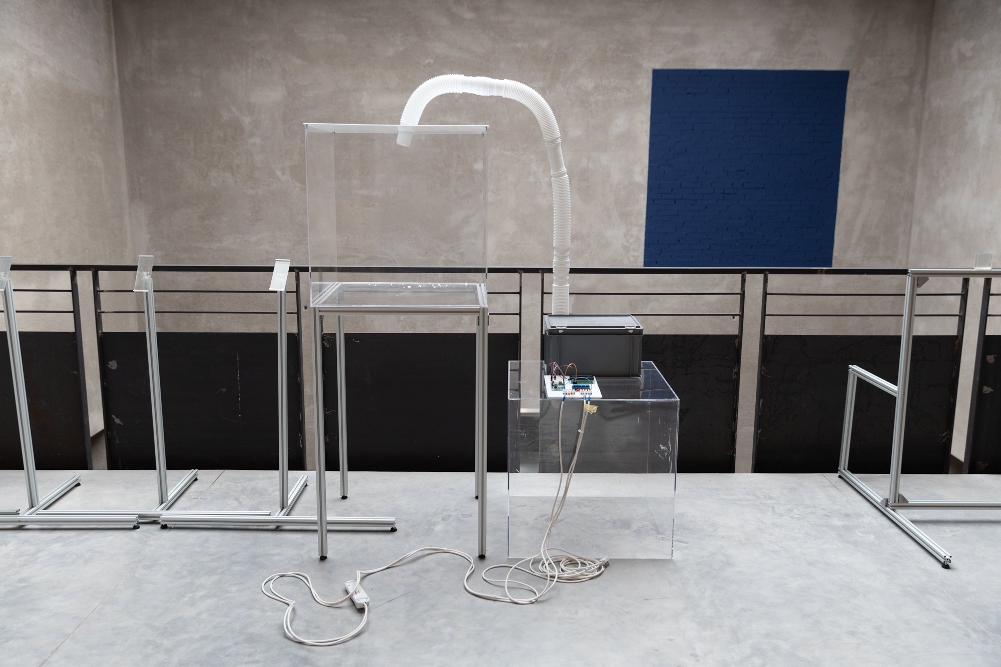
After some hours of work, this was final result:
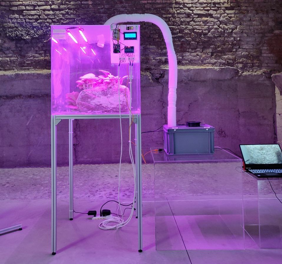
Pretty cool, isn't it? 😍
To download the slides of the project in order to have a global overview you can click here.
- Arduino UNO
- Breadbord, resistors, jumper wires
- DHT11 sensor
- LCD display
- 4-channel Relay
- 4 led grow lights
- Ultrasonic atomiser
- Fan (optional: potentiometer)
- Heat mat
- 4,7 KΩ resistor
- Power strip
Of course if you haven't it yet, you will need to install Arduino Software; detailed instructions for installation in popular operating systems can be found here.
First of all, you will need to connect the low voltage sensors to the Arduino UNO. The DHT 11 sensor allows us to measure the temperature and the humidity of an environment and it is composed by 4 pins as you can see in the following picture:
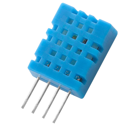
Where the meaning of the different pins is given by:
- VCC: 3.5V to 5.5V;
- DATA: outputs both temperature and humidity through serial data;
- NC: no connection (not used);
- GROUND: connected to the ground of the circuit.
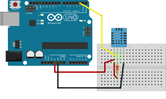
As an example of the electronic connections you could just copy the electronics of the following picture, but be careful: in our software implementation the pins connected are not the same! Eventually, just remember to look and change some small parts of the main code.
In the next step we have to connect the LCD display. We used an 20x4 character display with an onboard potentiometer which controls the brightness of the display. Altough we used a breadbord, an illustrative image of the connection is given by:
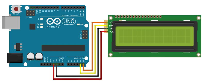
Often when we have to deal with displays in electronics, it is way more confortable to use libraries instead of coding everything by-hand. For this reason we implemeted the LCD display by using a library called LiquidCrystal_I2C.h for which you can install it from this simple repository. For the same reason we have used another library for the DHT11.
It is now time to consider the relay, an important device when we have to deal with "home" voltage electronics (220 V - 240 V). We have used a 4-channel relay for which we have two different side:
High voltage side
- NO: Normally Open
- COM: Common
- NC: Normally Closed
Low voltage side
- GND
- IN1: Atomiser
- IN2: Fan
- IN3: Light
- IN4: Heat mat
- VCC
We actually used Normally Open connections. That means, when we tell Arduino to output an HIGH signal the current will not flow. Otherwise, when we tell Arduino to output a LOW signal, the current will flow. I personally recommend this guide for those who did not understand how a relay works.
In the following photo you can see our original electronic connections:

In this photo, the cable at the left coming from the bottom of the image is directly connected with the electric socket of the building (220 V). In this cable we can see a blue wire that represents the phase of the circuit, i.e. it transports 220 V. Instead, the brown wire represent the neutral, i.e. on this conductor the voltage tends to 0 V. We then created a parallel circuit in which 4 neutral wires go into the 4 Normally Open connections of the relay. Finally, we connected all the 4 Common channel of the relay (with the phase of the circuit) in a power strip.

In this way, the relay could control the input voltage of the 4 electrical outlets of the power strip, like a switch! 😁
In the 4 electrical outlets of the power strip, we have connected the atomiser, the fan, lights and the heat mat. The ultrasonic atomiser has the aim to produce vapor. This can be done by just putting the atomiser inside a water container, meanwhile the fan is meant to displace the vapore created from the water container to the case containing the mushrooms. To optimize this process we involved a plastic tube.
Regarding the led lights, we just connected it to one of the electrical outlets of the power strip, and we did the same also for the other tools. We used a specialized led lights with a spectrum composed by white light (3000 K), blue (460 nm) and red (620 nm): the mostly absorbed bands by plants.

It is possible to see the whole code for the automated grow box here.
First of all, we loaded the libraries related to the sensors and we defined constants related to the minimum percentage humidity and the minimum temperature for the mushrooms.
Then, in the void setup() we setup the LCD display and we displayed the first message:
GROW BOX - PoliPolo
PLAM and Phylor for
LabAperto Ferrara
PopUp 29 APR 2022
Then we defined the measured parameters with using the function dht.readHumidity() and the function dht.readTemperature() contained in this library that we have mentioned before. Finally we basically printed the measured themperature and the measured humidity on the LCD display with the function lcd.print.
To control the electrical outlets we simply performed a for cycle for each of the 4 devices. For the atomizer and the fan, we simply ask to turn on them when the level of the humidity is too low (mushrooms like an environment with more than 80 % ho relative humidity). For the heat mat we ask to turn on the switch of the power strip when the temperature mesasured in the case of the mushroom is below 24 °C.
Meanwhile, for the led light management we thought to reconstruct the light cycle given by the sun: so basically we tried to turn the lights on for 12 hours and then turn them off for the next 12 hours. With an RTC sensor everything could have been easier, more efficient and more accurated, but we hadn't one. For this reason we just used the function millis () to define a variable called myTime. Starting withe the led lights turned on, if the variable myTime reaches the value of 43200000 (ms) it means 12 hours are passed and we can turn down lights. If then the variables reaches 86400000 (ms) it means 24 hours are passed from the first run of the code and we can impose the end of the loop with the function interrupts ().
With this implementation every day we add an error of 30 seconds.
I would like to thank guys from PLAM Creative Studio that gave me the opportunity to help them for this project, but also the Laboratorio Aperto di Ferrara that gave us the location to work on this project. I also would like to thank Giuseppe Baldazzi, the professor of Electronics for Applied Physics course that allowed me to use this project as an exam.
See you for the next project! 😊