Reference System
The electrical system for the reference car has been modified due to part availability. The original system can be seen here.
Documentation on the mechanical system can be found here.
Modifications to the original electrical design were done to accommodate the new chassis. The original magnet chassis allowed the pwm controller to plug into the car`s electrical system for control. With the ruckus, the rc, voltage regulation, and motor controller were integrated. This did not allow interface to the pwm controller. The original ruckus controller was removed and a voltage regulator and motor controller were added.
- Chassis
- Raspberry Pi 3
- Wide Angle Camera
- PWM Controller
- D24V150F5 Voltage Regulator
- VNH5019 Motor Driver
- 3S 5.2 Ah Lipo Battery
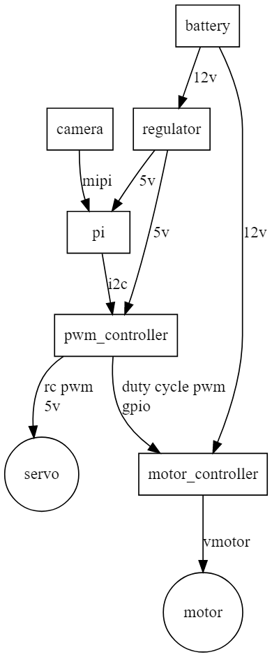
Battery connects to regulator and motor driver.
The camera connects through mipi to the raspberry pi.
The regulator produces 5v for use by the raspberry pi and the pwm controller.
Raspberry pi connects to pwm controller via i2c.
PWM controller provides 5v power to steering servo. It commands steering angle using rc style pwm signal.
PWM controller commands vehicle throttle by communicating to the motor controller using duty cycle style pwm. Motor direction is permanently set by connecting direction io to 5v and gnd.

The major components. Battery is missing.
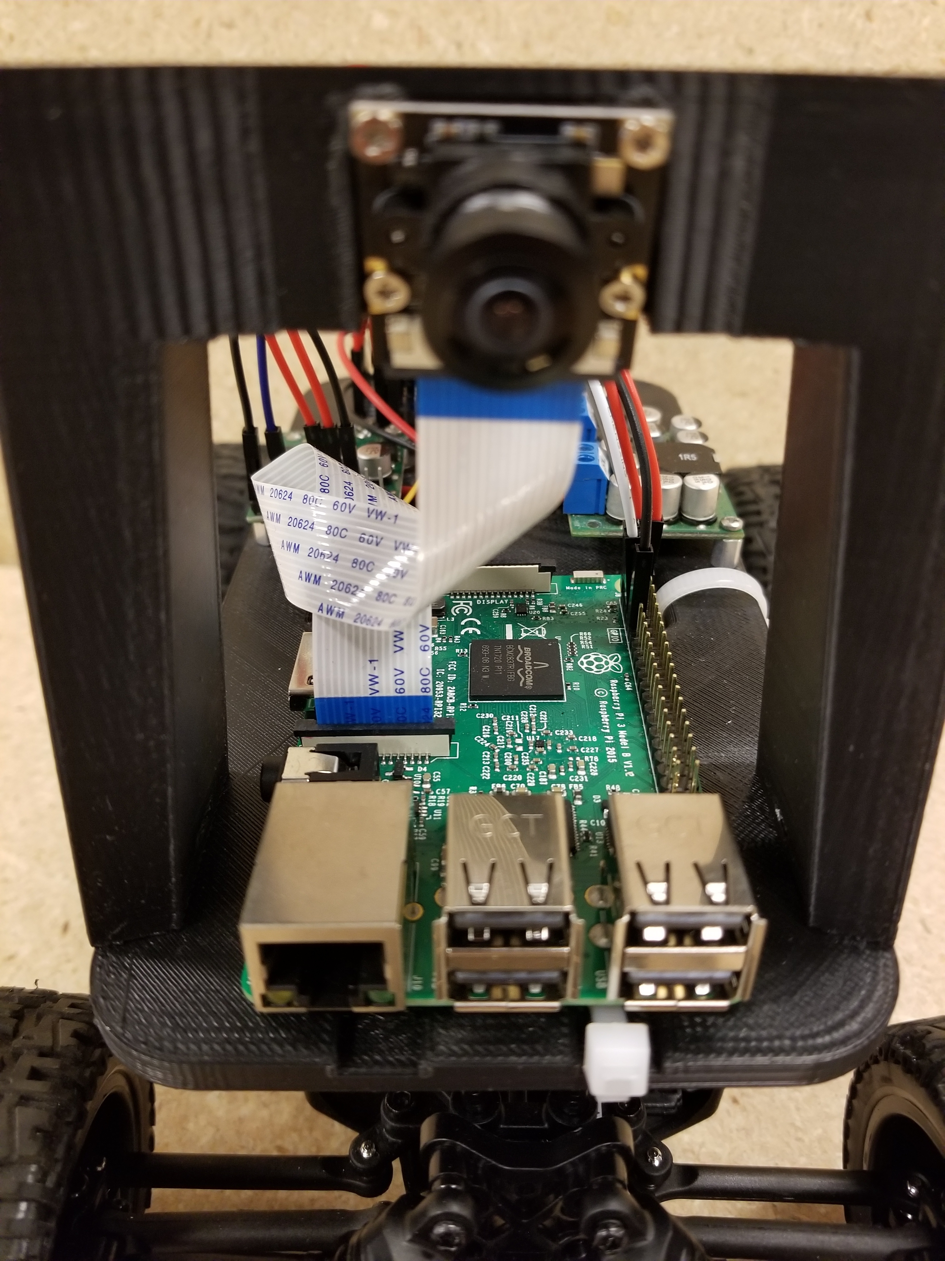
Camera connected to raspberry pi 3. Camera connector on the pi3 in in the front, not the back.
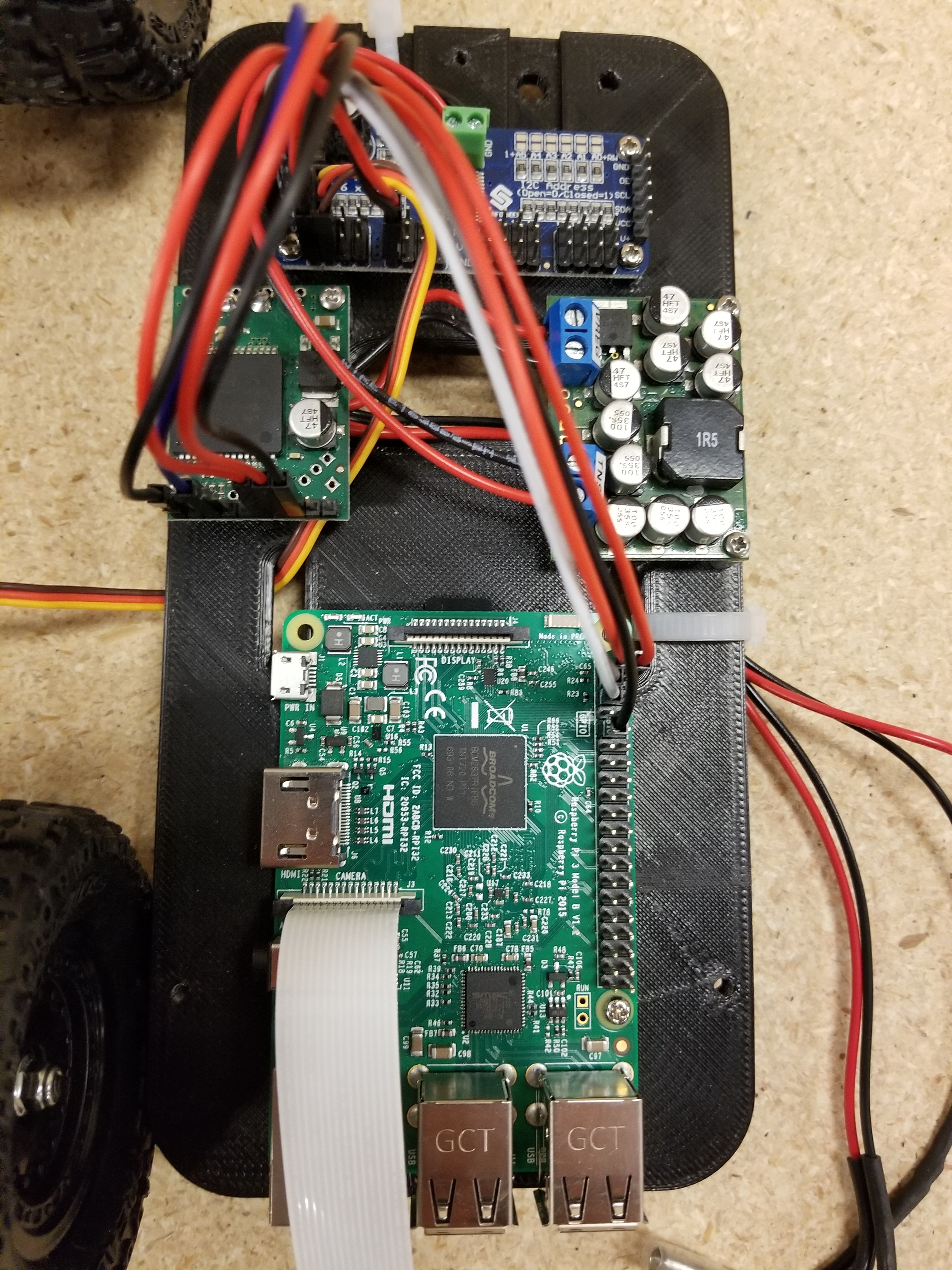
Close up of some of the wiring.
Ruckus throttle motor seems to consume between 2A and 3A at 10V to 12V.