In this project, my goal is to write a software pipeline to identify the lane boundaries in a video from a front-facing camera on a car.
Advanced Lane Finding Project
The goals / steps of this project are the following:
- Compute the camera calibration matrix and distortion coefficients given a set of chessboard images.
- Apply a distortion correction to raw images.
- Use color transforms, gradients, etc., to create a thresholded binary image.
- Apply a perspective transform to rectify binary image ("birds-eye view").
- Detect lane pixels and fit to find the lane boundary.
- Determine the curvature of the lane and vehicle position with respect to center.
- Warp the detected lane boundaries back onto the original image.
- Output visual display of the lane boundaries and numerical estimation of lane curvature and vehicle position.
Two Changes made from the last time I submitted
- Updating the Color Space Binary Selection, I switched XHL Binary which is nothing but HLS+ Sobel Filter.
#finding color space
combined_binary = xhl_thresh(warped, (5, 100), (18, 50), (195, 255))
- Changing the Center Offset calculation
distance = round(((left_lane[-1] + right_lane[-1]) / 2 - 320) * 3.7 / 700, 2)
Here I will consider the rubric points individually and describe how I addressed each point in my implementation.
1. Briefly state how you computed the camera matrix and distortion coefficients. Provide an example of a distortion corrected calibration image.
The code for this step is contained in the first code cell of the IPython notebook located in "./Advanced_Lane_lines.ipynb" from 3rd Cell
function python def camera_calibration(images, nx, ny):
Here the images for camera calibration are taken from folder camera_cal using glob function we will read all the images assuming all images belongs to chess board. Once the images are read we can make use of the function camera calibration function to calibrate the camera.
def camera_calibration creates objp numpy array with 9x6 = 54 points starts from 0,0... 8,5. Loop over the images, convert the images to Gray using cv2.cvtColor function. Now we need to find the corners in the 9x6 board using the cv2.findChessboardCorners function. Once the call for the above is successful we append 3d points in objpoints & imgpoints in image plane.
once we have objpoints and imgpoints we can now calibrate using the cv2.calibrateCamera function Which returns the camera matrix(mtx), distortion coefficients(dist), rotation(rvecs) and translation vectors(tvecs) More information about the cv2 function is here. OpenCV Docs

I start by preparing "object points", which will be the (9, 6, 3) coordinates of the chessboard corners in the world. Here I am assuming the chessboard is fixed on the (9, 6) plane at z=0, such that the object points are the same for each calibration image. Thus, objp is just a replicated array of coordinates, and objpoints will be appended with a copy of it every time I successfully detect all chessboard corners in a test image. imgpoints will be appended with the (9, 6) pixel position of each of the corners in the image plane with each successful chessboard detection.
I then used the output objpoints and imgpoints to compute the camera calibration and distortion coefficients using the cv2.calibrateCamera() function. I applied this distortion correction to the test image using the cv2.undistort() function and obtained this result:

To demonstrate this step, I will describe how I apply the distortion correction to one of the test images like this one:
Here I have taken the test images from the test_images folder and Chessboard from camera_cal folder.


2. Describe how (and identify where in your code) you used color transforms, gradients or other methods to create a thresholded binary image. Provide an example of a binary image result.
I used a combination of color and gradient thresholds to generate a binary image. Look at the following python functions about the color spaces I explored.
| Function name | Description |
|---|---|
abs_sobel_thresh |
Sobel Filter. |
mag_thresh |
Magnitude of Gradient ! |
Combined Gradient |
Magnitude, Sobel, Direction |
rgb_thresh |
Color Space :RGB |
hls_thresh |
Color Space :HLS |
hsv_thresh |
Color Space : HSV! |
combined_color |
Combined Color + Binary |


As you can see after trying out all the different color spaces such as RGB, HLS, HSV I settled for Combined color code is as shown below
Finally I ended up choosing the XHL Binary space code for the same is given below
def xhl_thresh(img, x_thresh, h_thresh, l_thresh):
    hls = cv2.cvtColor(img, cv2.COLOR_RGB2HLS)
    h = hls[:,:,0]
    l = hls[:,:,1]
    h_binary = np.zeros_like(h)
    h_binary[(h > h_thresh[0]) & (h <= h_thresh[1])] = 1
    l_binary = np.zeros_like(l)
    l_binary[(l > l_thresh[0]) & (l <= l_thresh[1])] = 1
    hl_binary = np.zeros_like(l)
    hl_binary[(h_binary == 1) | (l_binary == 1)] = 1

    sxbinary = abs_sobel_thresh(img, 'x', 5, x_thresh)
    xhl_binary = np.zeros_like(sxbinary)
    xhl_binary[(hl_binary == 1) & (sxbinary == 1)] = 1

    return xhl_binary
3. Describe how (and identify where in your code) you performed a perspective transform and provide an example of a transformed image.
After doing some trial and error with image sizes and trying to draw the Region of Interest and the perspective transform points I decided to manually set it so that it is easier to modify following is the source and destination of the perspective Transform:
left_bottom = (150, 672)
left_top = (580, 450)
right_bottom = (1200, 672)
right_top = (730, 450)
roi_points = [[left_top, right_top, right_bottom, left_bottom]]

dst = np.float32([[0, 0], [640, 0], [640, 720], [0, 720]])


This resulted in the following source and destination points:
| Source | Destination |
|---|---|
| 150, 672 | 0 , 0 |
| 580, 450 | 640, 0 |
| 1200, 672 | 640, 720 |
| 730, 450 | 0, 720 |
I verified that my perspective transform was working as expected by drawing the src and dst points onto a test image and its warped counterpart to verify that the lines appear parallel in the warped image.
4. Describe how (and identify where in your code) you identified lane-line pixels and fit their positions with a polynomial?
After applying calibration, thresholding, and a perspective transform to a road image, I take a binary image where the lane lines stand out clearly. However,I still need to decide explicitly which pixels are part of the lines and which belong to the left line and which belong to the right line.
I first take a histogram along all the columns in the lower half of the image like this: XHL Histogram
import numpy as np
import matplotlib.pyplot as plt
histogram = np.sum(img[img.shape[0]//2:,:], axis=0)
plt.plot(histogram)```
![Histogram][image22]
##### Sliding Windows
With this histogram I am adding up the pixel values along each column in the image. In my thresholded binary image, pixels are either 0 or 1, so the two most prominent peaks in this histogram will be good indicators of the x-position of the base of the lane lines. I can use that as a starting point for where to search for the lines. From that point, I can use a sliding window, placed around the line centers, to find and follow the lines up to the top of the frame.
![Sliding Windows][image15]
#### Ploynomial Fit
Polynomial Least Squares comprises a broad range of statistical methods for estimating an underlying polynomial that describes observations.

My implementation can be found in the function
```python
def polynomial_fit(warped, left_indices, right_indices, left_fit, right_fit):
def modified_windows(warped, left_fit, right_fit):
5. Describe how (and identify where in your code) you calculated the radius of curvature of the lane and the position of the vehicle with respect to center.
Calculation of Radius of Curvature of Lane is extensively discussed in the Class Materials.The radius of curvature are calculate by following equation:
R = [1 + (2Ay + B)^2]^3/2 / |2A|
the postion to center is the distance between middle of image(640) and the middel of lane lines at the bottom.

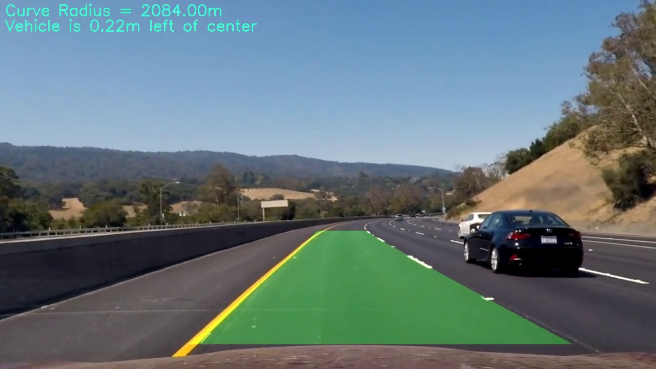
6. Provide an example image of your result plotted back down onto the road such that the lane area is identified clearly.
You can run the in[29] cell in the ipynb notebook and findout the implementation. The steps are as follows
-
Read an image, undistort, find out Region of Interest, get the Warped version using
image_unwarpand then used thecombined_binary -
Find out the left & right indices using the
sliding_windowfunction -
Get the polynomial fit and get the
left_polyandright_poly -
Calculate the lane using
calculate_lane -
Find the curvature using
curvature_distance -
Draw the lane using the
draw_lane -
Draw the Final image using the
draw_final

1. Provide a link to your final video output. Your pipeline should perform reasonably well on the entire project video (wobbly lines are ok but no catastrophic failures that would cause the car to drive off the road!).
Here's a local file
1. Briefly discuss any problems / issues you faced in your implementation of this project. Where will your pipeline likely fail? What could you do to make it more robust?
Here I'll talk about the approach I took, what techniques I used, what worked and why, where the pipeline might fail and how I might improve it if I were going to pursue this project further.
1. Finding the Suitable Color Spaces for Lane Recognition I initially struggled to find suitable color spaces and binary combination for the lane recognition, I tried RGB, HSV, LAB, YCRB all independently. I spent most of time trying to find the right color + binary combination but each of the color spaces had one or other problems, whichever showed clear marking of lane in one test image would eventually wear out during next test image. So I did explore other possibilies I saw in one of the slack channels, student mentioned combining the color, which is what I did eventually.
2. Shadows Causing lane recognition to fail at some places In the harder challenges there were lot of shadows around so I thought of exploring this to see how we can detect lanes in shadows. I read little bit about it one of the option is to use the CLAHE histogram equalization which I used during my project, this is known to give better hold of the shadow environment. This is something in my todo list
3. Bumpy Roads causing the Lane recognition to go Haywire I saw in some places my lane detection went haywire, this happened when the Roadsurface suddenly changed or I guess vehicle hit a rough patch suddenly jumped? I can't tell But this is something that needs to be handled !! Again one more in my todo list.
4. Visibility/Weather and other conditions. I didn't really factor in the weather, Visibility and other conditions, which can definately have more impact, Color of the road surface something which is not widely discussed. How does the Car behave on mud roads ? how can we detect lanes if there is lot of sunshine etc.
5. ROI, Curvature, Lane detection Tuning Calculating the ROI is handcoded to the point, which I think should be dervied from the image sizes rather. Lane detection tuning took lot of time, trying to evaluate whether we have best fitting polynomial or is there a deviation etc.