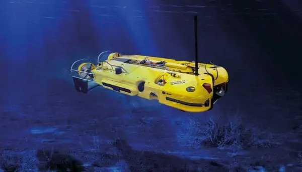
A remotely operated underwater vehicle is tethered underwater mobile device, also called underwater robot.
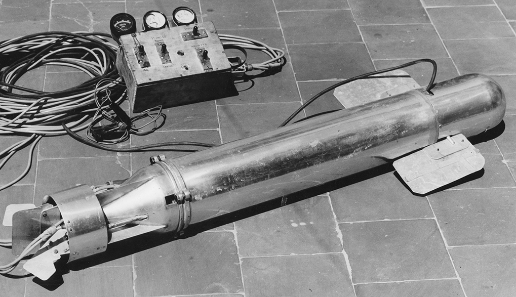
The first ROV ever built was the Poodle made in 1953 by Dimitri Rebikoff, a French pioneer in dive equipment and photography. The Poodle wan unmanned adaptation of his dive scooter with a tether and surface controls.
The U.S Navy started using ROVs in 1960 for recovery of underwater equipment, then by the 1980s there were more than 500 ROVs around the world, many of them being used in commercial applications.
In the ROV world, the vehicles are ussualy broken into size ccategories, which also correspond with capabilities.
| Hull with Open frame | Frameless hull (close hull) | |
|---|---|---|
| Structure Type |  |
 |
| Seaeye Falcon | SAAB Double Eagle SAROV | |
| Advantage | Well known structure adopted on most ROV | Greater mobility/highly manoeuvre |
| Stable 3DOF translational motions based on large metacentre | Typically lightwewight and portable | |
| Large payloads and can carry object | More energy efficient | |
| Disadvantage | These types of ROV have difficulties with motions requiring more than 3DOFs | Smaller paylaod |
| Not convenient for attaching tool or equipment |
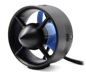
The most common form of marine propulsion system for ROV is the marine thruster. Underwater thrusters are propulsion devices that combine a propeller with a hydraulic or electric motor.
Underwater gliders use a different form of propulsion known as variable-buoyancy propulsion. This method utilises an internal bladder that can be inflated or deflated to change the density of the vehicle, making it ascend or sink as required. The glider uses hydrofoils to generate forward motion as the vehicle descends, with the result that the movement pattern of the glider resembles a sawtooth profile.
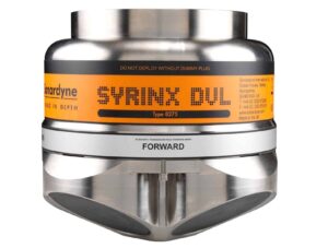
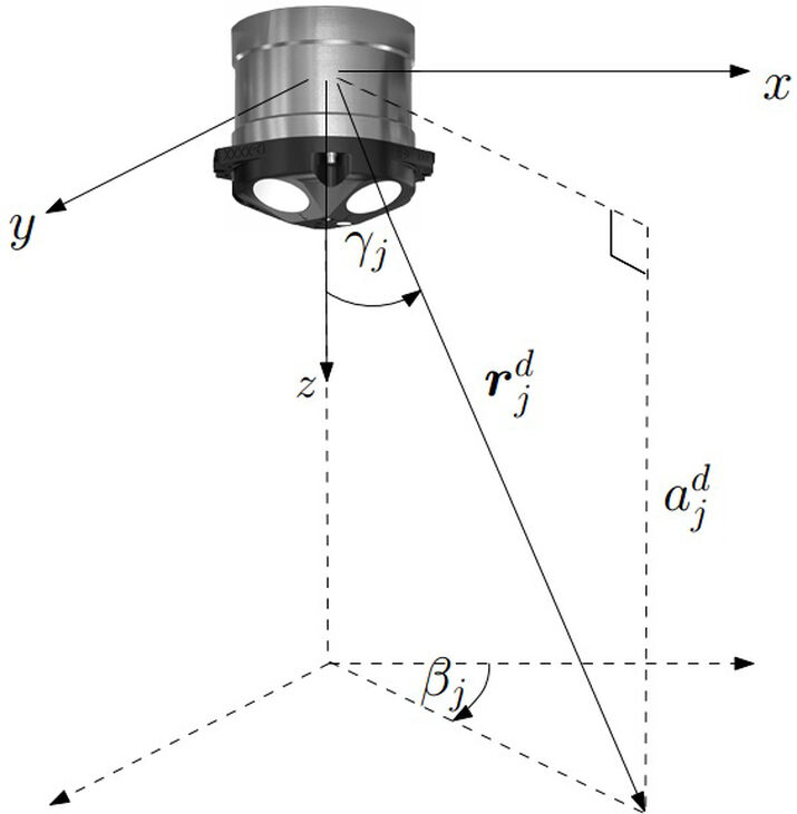
The Syrinx Doppler Velocity Log (DVL) is a 600 kHz system designed for both unmanned surface and subsurface vehicles that can be used as a standalone DVL, as part of an integrated system, or perform both functions at once. This dual capability means that only one DVL/altitude sensor is required for both ROV control and survey crews, saving on cost and payload space.
Ranger 2 Subsea Positioning (USBL) System
Designed for deep and shallow-water tracking of subsea vessels and with an operating range of greater than 7000m, the Ranger 2 is a high-performance USBL (Ultra-Short Base Line) subsea vehicle positioning system that provides an optimal accuracy of better than 0.1%. Ranger 2 can simultaneously track multiple subsea targets or transponder nodes and upload data to the surface with high-speed communications. It is ideal for a wide range of ROV or AUV missions including surveying, ocean science and seismic exploration.
Solstice is a Multi Aperture Sonar (MAS) system designed for high-precision AUV missions such as Search, Classify and Map (SCM), hydrographic surveys and mine detection. Capable of producing high-fidelity imagery and with an industry-leading along-track resolution of 0.15°, Solstice provides superior performance even in very shallow water, and consumes only 18 Watts of power, making it ideal for extended unmanned missions. Powerful onboard processing produces geo-coded side-scan imagery for integrated Computer Aided Detection and Classification (CAD/CAC) and Automatic Target Recognition (ATR). A vertical hydrophone array on each flank delivers high-quality bathymetry data which can be used to produce extremely detailed digital terrain maps.
Steep underwater walls are often important to investigate for multiple scientific end users such as biologists and geologists, as well as professionals in industrial sectors. However, surveying and mapping of such walls has been challenging due to technical limitations.
Researchers at the Norwegian University of Science and Technology (NTNU) have now found that a horizontally-facing DVL is key to solving mapping challenges, while it also reduces the need for highly skilled manual ROV operators.
Researchers at the Centre for Autonomous Marine Operations and Systems (NTNU AMOS) have now developed an ROV-based system for efficient, high quality visual mapping of a steep underwater surface.
Researchers at the Centre for Autonomous Marine Operations and Systems (NTNU AMOS) have now developed an ROV-based system for efficient, high quality visual mapping of a steep underwater surface.

Because this approach relies on sensors that are common to the majority of ROVs, it could easily be adapted to a wide range of ROVs, reducing reliance on highly skilled manual operators. An efficient post-processing strategy using commercially available software was applied to the collected data, further reducing the required resources for the end user.

WaveShare 10-DOF Inertial Measurement Unit (IMU) is used as a motion sensor. This sensor is consisted of MPU9255 (3-axis gyroscope, 3-axis accelerometer, and 3-axis magnetometer) and BMP180 (barometric pressure sensor). Accelerometer is used for measuring ROV’s acceleration. Meanwhile, gyroscope is used for measuring ROV’s position orientation and accelerometer correction purpose. Magnetometer is used as digital compass for direction/heading.
The system is divided into three parts: a software for ground control station, Wi-Fi connected action camera, and IMU sensor’s data transmitter. To reduce the computing requirements on the sensor node, raw sensor data in transmitted. The sensor data transmitter managed the output from sensor data into a data package and sent it to Wi-Fi module which will sent it to the receiver.

The customized business optical transmission terminal uses fiber multiplexing technology to realize 2 way analog video, 2 physical isolation, 100M line speed Ethernet, audio, RS485/RS232 data and switch volume and other signals in the same optical fiber transmission line. The equipment is cylindrical design, wide and wide temperature and pressure can be applied to the sealed bin of a cable underwater robot and so on. It is an important part of the underwater equipment with cable.

The vLBV requires 350 VDC power. The Surface Power Supply (SPS) converts the shipboard/shore/generator/inverter 100-265 VAC into 350 VDC for the ROV and adjusts the voltage above 350 VDC as needed to compensate for electrical losses, which can occur over the length of the tether. The SPS was designed to be environmentally hardened for operation from small boats and environmental exposure including rain. To accomplish this, the AC to DC converters are encapsulated inside a weather resistant case.