Design is done with FreeCAD (Plywood-7-Segment-Digital-Clock.FCStd). This file contains all the source models for 3D printing and the paths for CNC machining (you might have to re-create the paths for your CNC machine but you can use the FreeCAD file for this). My paths are generated to use with a GRBL based machine.
This work is licensed under a Creative Commons Attribution-NonCommercial-ShareAlike 4.0 International License.

Connect 5 volts from the micro usb breakout board to the 5 volt (VIN) pin on the ESP module.
Connect Ground from the micro usb breakout board to the Ground on the ESP module.
Connect 5 volts from the usb breakout board to 5 volt on the LED strip.
Connect Ground from the usb breakout board to Ground on the LED strip.
Connect pin D6 from the ESP module to the Data line on the LED strip.
Connect pin D8 from the ESP module to one side of the button and connect the other side of the button to 3.3V of the ESP module.
To power the clock you can use a regular 5V 2A power supply.
| Components |
|---|
| ESP8266 Wi-Fi module |
| USB break out board |
| 5V 2A power supply |
| Wires |
| Mini breadboard |
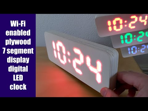
| 58x WS2812B LED |
Check the YouTube video for the order how to wire and solder them together because this is mirrored to the following diagram:
    47 46        33 32            17 16        3  2
  48     45    34     31        18     15    4      1
  49     44    35     30   29   19     14    5      0
    57 56        43 42            27 26       13 12
  50     55    36     41   28   20     25    6     11
  51     54    37     40        21     24    7     10
    52 53        38 39            22 23        8  9