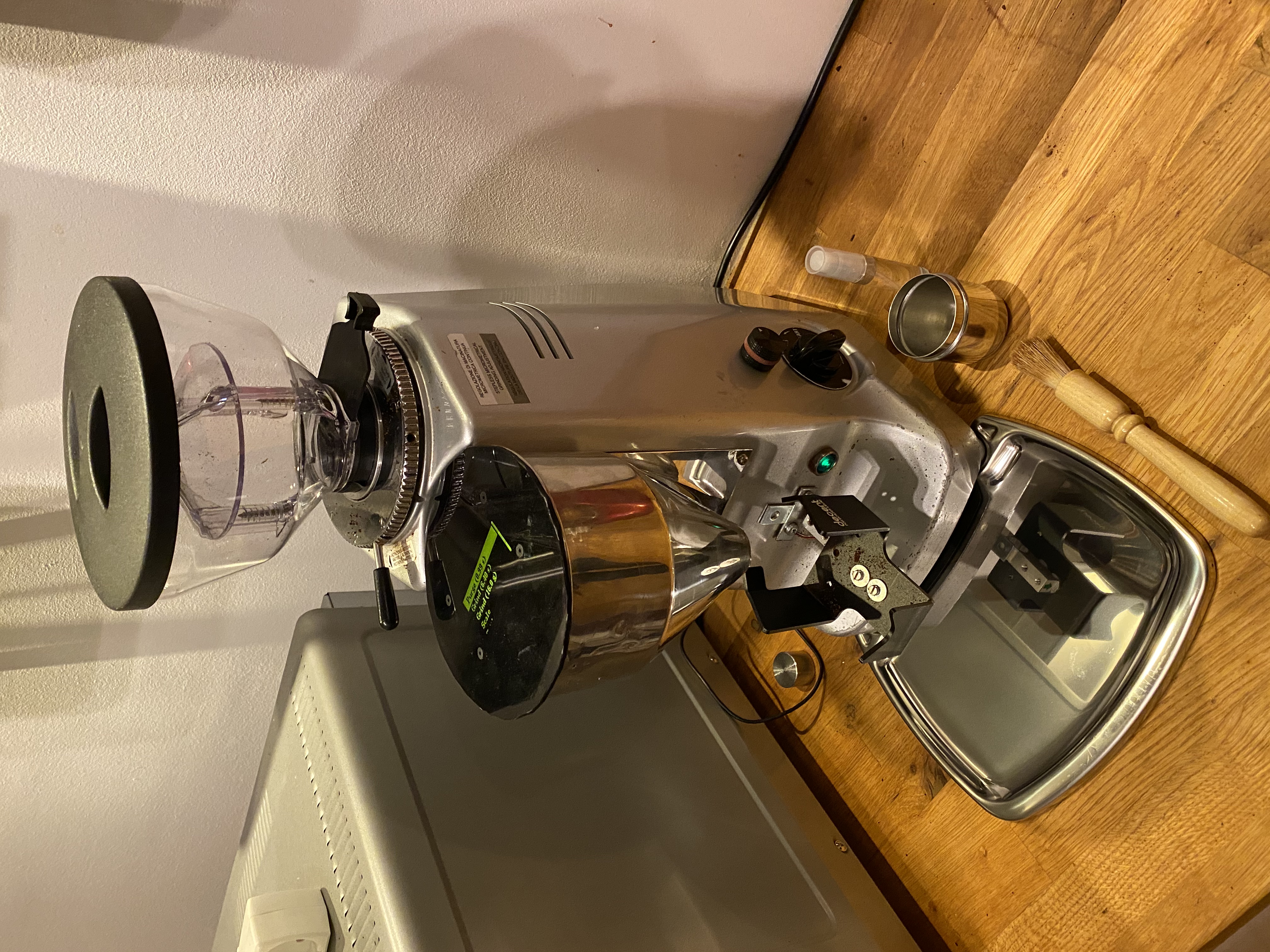
A grinder controller for my Mazzer Major
This project is in use and development. Current PCB Revision is Rev C.
There will be a Rev D PCB. The Rev D PCB will adjust the fit for a Futurekit FB20 box (it's currently slightly too large, and the mounting holes are misaligned).
- Rev A: First revision board
- Rev B: Substantial changes. ADS1232 load cell interface, SMT components, fully populated UEXT connector (was printed).
- Errata: Resistor R2 never should have existed. Remove R2 or cut trace from R2 to GND.
- Errata: R3 and R4 silk screens are flipped around. They're the same value though, so it doesn't make any material difference.
- Rev C: Removed the resistor that was R2 in Rev B (hasn't been printed), fixed silk screen, added dots for SMT ICs.
- Errata: Doesn't quite fit in the intended Futurekit FB20 box.
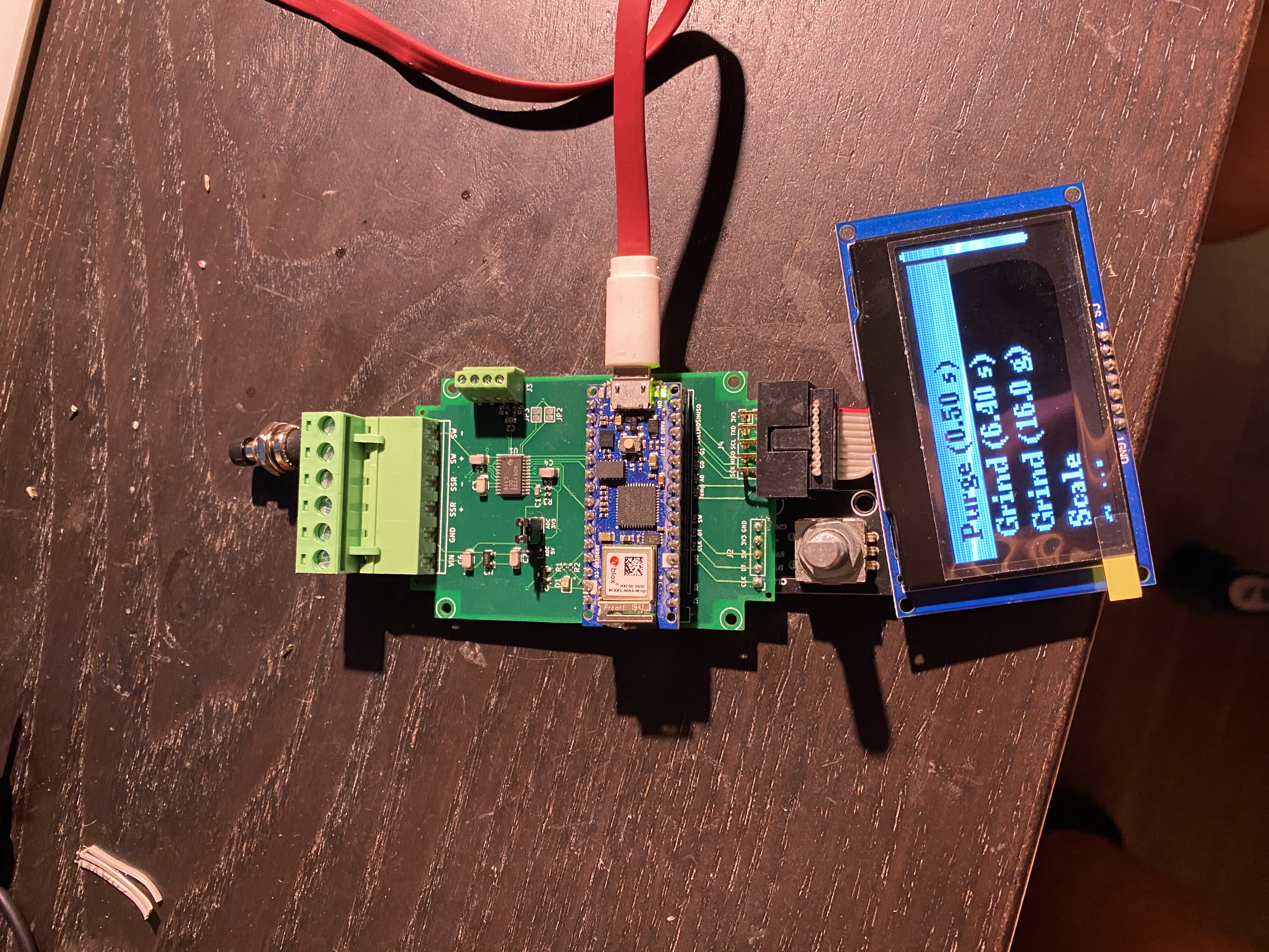
This is an Arduino based grinder controller for my Mazzer Major. It has a display and is controlled by a rotary encoder. It also contains a PCB schematic.
- Grinder control via a simple to use interface, controlled by a rotary encoder
- Timed grinding
- Grind by weight
- An ADS1232 load cell interface, sampling a load cell at 80 SPS.
- High accuracy
- Fast taring
- Arduino Nano 33 IoT
- A Solid-state relay
- I'm using a Fotek SSR-40 DA clone, because that's what came with my used grinder when I bought it
- If you want a more high-quality component, a Crydom-Sensata 84137000 would be a good choice
- A high quality 5.3-6.0V power supply. I'm using a Mean Well RS-15-5. Quality matters for minimizing ADC interference. A 5V power supply with an adjustment potentiometer should do fine, the LDO will regulate anything between 5.3 and 6.0 V to 5V for the ADC. Set your PSU to 5.5V and all will be good.
- A KY-040 style rotary encoder
- An SSD1309, SPI connected, 3.3V, 128x64 px OLED
- A 1000 g whetstone bridge load cell
- 1 x DIL socket 32 pin (remove 2 pins, optional but recommended) (For the Arduino)
- 1 x PCB pin header 5.08mm 6-pole right-angle (For power, SSR and manual grind knob connection)
- 1 x IDC box header PCB 10-p 2.54mm (For display connection)
- 1 x Screw terminal 2.54mm 4-pole (For load cell connection)
- 1 x 5 pin 2.54mm pin header (For rotary encoder connection)
- 1 x 3 pin 2.54mm pin header (For ADC debug voltage jumper)
- 1 x 2.54mm jumper
While not technically part of the board, you'll probably want some other things to make it all work:
- 1 x Screw terminal pluggable 5.08mm 6-pole
- 1 x 10 pin IDC flat cable
- 1 x 5 pin jumper wires
- Wiring
- 0.75 mm² (or higher) copper wiring for the high voltage side
- Preferably in standard colors, which would be blue/brown in Europe for neutral/load. Signal wire from SSR to the motor can be any other color except green/yellow. Orange is a good choice.
- Wiring cable, I'd go for 0.20 mm² copper. Preferably in red and black.
- 0.75 mm² (or higher) copper wiring for the high voltage side
- WAGO 221 splicing connectors
- A 100.0 g reference weight for scale calibration