Cybrid is an open-source MIDI controller.
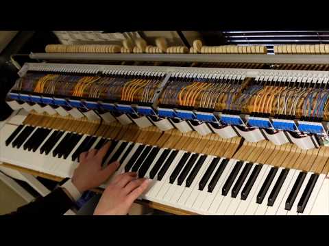
Cybrid is based on a DIY project Evgeni Kumanov (AKA CyberGene) created in 2020 for turning a grand piano action into a MIDI controller. In the digital piano terminiology, instruments with a real wooden piano action are called hybrid pianos, hence the name Cybrid (from CyberGene and hybrid), as one member on the PianoWorld forums suggested. Here's a demo of the finished controller (Ctrl-click on the picture to open the YouTube video in a new tab):
In its initial state this GitHub project contains just the PCB design, the software and the mechanical considerations/descriptions of that DIY project. It may be used as it is for anyone willing to recreate that project or can evolve into a more advanced and improved design that can be used for other (hybrid or regular) MIDI-controllers, etc.
Update: There's now a great project by Jay Kominek who is a software developer with a background in embedded development and electronics. His project is inspired by Cybrid but is apparently better designed from the ground up: https://github.com/jkominek/piano-conversion/
The goal of the project is to detect the velocity of the hammers and turn it into MIDI velocity. This is realized by using Vishay CNY70 optical sensors and Texas Instruments LM339 voltage comparators (LM339AD package).
The main principle of using voltage comparators to turn continuous analog signal into digital binary signals has been suggested by Marcos Daniel, a member of the PianoWorld forums. Everything else, including the multiplexing, PCB design, Teensy code and integration with a real grand piano action has been done by me. Before starting this project I had almost no prior knowledge of electronics, PCB design and microcontrollers which is why many design decisions are probably far from optimal. Hopefully smart guys can improve and optimize it further.
- The CNY70 is an optical proximity sensor that consists of a photoemitter (a LED) and a phototransistor. The phototransistor will change its collector current depending on the proximity of subjects to the sensor
- By measuring the voltage drop created by the collector current on a resistor and comparing it to a reference voltage, we will know whether the subject is within a predefined proximity.
- A voltage comparator is a device that has two voltage inputs and a digital output. One of the inputs is a reference voltage selected through a trimpot and the other input is the phototransistor output voltage. If the phototransistor output voltage is higher than the reference voltage, the output of the comprator will be digital 1, otherwise it will be digital 0.
- Thus we can turn the continuous analog sensor signal into discrete digital binary value that is determined by whether the subject is closer than a predefined distance
This is important because the LM339 voltage comparator is very fast when comparing two voltages. It takes just a few nanoseconds for the comparator to switch its digital state. This will allow for a very fast detection of distance, in the sense of "the hammer is at the predefined distance (or closer)", i.e. the comparator will provide a digital output of 1 whenever the hammer crosses that distance and stays closer to the sensor, and will switch back to zero when the hammer crosses that point on its way back and moves away from it. By using this principle, we can avoid slow analog-to-digital conversion. (As you will see in the following paragraphs, scanning through all the 88 keys of a piano, i.e. detecting hammer position at multiple proximity positions in a loop won't work if we rely on proper ADC-conversion because most programmable controllers such as Arduino/Teensy, etc. have only a few (1 or 2) ADC chips and a single conversion takes microseconds which would cumulatively lead to inability to scan the entire keyboard without introducing huge latency and without missing the very fast hammer motion. Even if fast ADC-s are used, it will require that we multiplex analog signals and that's not a trivial task)
So, we can configure two distance points through two trimpots and two voltage comprators. We will have two digital outputs from the two comparators and by measuring the time it takes for the hammer to pass between the two points (i.e. the comprators' outputs switch from 0 to 1), we can calculate velocity.
A standard way of reading multiple sensors through limited number of inputs is through multiplexing, i.e. using specialized chips that can (roughly speaking) switch between multiple inputs and channel them through a single line. However a particular problem with this approach is that there is a switch delay and in this particular implementation scanning speed is of highest importance. To work around this we can use a programmable controller with as many inputs as possible, and that's Teensy USB Development Board. It has 58 digital input/output lines.
We can gather multiple scanned notes into a group, then select a group, read all the sensor data (each sensor outputting two digital signals corresonding to two distances, as seen above), then switch to the nextg group, etc. until we read all notes. In the current implementation, for a 88-key piano, we have 3 binary signals per note (see below why 3 and not just 2) and a group is made of 5 notes. This means we have 18 groups (the last group only contains 3 notes and not 5):
18 groups x 5 notes = 90 notes (-2 unusued in the last group) = 88 notes
3 signals per note = 15 signals per group
18 groups x 15 signals = 270 binary signal lines
Now, if we can enable only one group at a time, we can then read the 15 signals from each group by reusing one and same 15 input signal lines. Thus we will have 18 group enable lines from the Teensy (outputs) and 15 input lines shared by all the 18 groups.
18 outputs + 15 inputs = 33 digital input/outputs.
Seems like we can go without using a mux/demux chips. Instead we will share inputs between groups. However the problem is if we just wire the corresponding inputs of the groups and since they will continuously generate differing signals (one group can generate high signal at the same time another group will generate low signal), this means they will be short-circuiting themselves. To avoid this we will use digital transceiver chips. A transceiver is a simple device that has a certain number of digital inputs and digital outputs. It will repeat on the outputs the same digital signal that it has on the corresponding input. However each chip has also an enable/disable line. When in disabled state, the outputs will be in high impedance state (regardless of input signals). This is how we solve the problem of short-circuiting. For the current solution we use SN74LVC245A Octal Bus Transceivers With 3-State Outputs (SN74LVC245ADWR package).
There are three types of printed circuit boards
- Sensor PCB - these are very small PCB-s each containing a single CNY70 sensor and placed above each hammer shank base. In a 88-key piano there will be 88 of these. 5 of these connect to a single Note PCB.
- Note PCB - these are the group modules. Each one serves 5 Sensor PCB-s. Each Sensor PCB is connected through three wires (5V, signal, GND). There are three trimpots per sensor PCB, for setting the predetermined detection distances. The uppermost trimpot is for sensor 1 which is the closest distance to the hammer stop rail. The Note PCB-s also contain a jumper that is set to one of 18 positions to determine the group number of the Note PCB. Note PCB-s also have an IDC34 socket. The Note PCB-s should be aligned on a horizontal line and be connected through a single IDC34 cable that has 18 IDC connectors. Each Note PCB has two power sockets. Each power socket has three lines (5V, 3.3V, GND). The two power sockets are wired to each other so that one can be used as power input and the other as power output for chaining to the next Note PCB. There are two voltages because the CNY70 sensors and the comparators are powered by 5V, however the digital signals from the transceivers as well as their power supply is 3.3V. The Teensy 3.6 controller supports only 3.3V voltage (unlike Teensy 3.5 and older but they are slower)
- Teensy PCB. This one contains the Teensy controller, an IDC34 socket for controlling the Note PCB-s, power inputs/outputs to chain to the Note PCB-s, and possibility to connect other devices (e.g. a sustain half-pedal to the analog inputs.) It has s USB-B input that's used only for power input. The Teensy controller itself has a micro-USB for connection to the computer to transmit MIDI. The Teensy controller itself is powered through that USB connection. Everything else requires an external power, for instance using the USB-B input socket. In the current implementation an iPad charger is used and it's sufficient to provide 2W of power which is the entire consumption. On the Teensy PCB there's also a jumper that can draw 3.3V power from the Teensy controller and send it to the Note PCB-s, however that's not recommended since there might be short circuits or problems with the Note PCB-s that can burn the Teensy. In the current implementation a pretty simple 3.3V voltage regulator is added through a small customized breadboard attached to the Teensy PCB, drawing from the 5V power.
The PCB-s are designed in the free KiCad editor.
To Be Done (a BOM or list with exact elements)
The program is written in the Arduino compatible language of Teensyduino. It would sequentially enable each Note module (a note module is serving 5 notes x 3 inputs). For each module all the 15 inputs are being read. For each optical sensor there are three predefined sensor distances (set through trimpots and with the calibration utility programs) that are referred to in the code as sensor1, sensor2, sensor3. Sensor3 corresponds to the damper being removed from the string, it is halfway from the hammer travel. Sensor 2 is where escapement happens. Sensor1 is where the hammer touches the rail (in reality it should be a bit further to allow for the scanning logic to catch that moment because the hammer will rebound quickly and sensor1 will be activated for only a brief moment).
Active low logic is being used.
Sensor distance signal lines are being active as long as the hammer is at this distance or closer to the rail. This means when sensor1 is active (low), sensor2 and sensor3 are also active, etc.
When the hammer activates sensor2 for the first time, it means we "start" measuring duration and we remember the timestamp of that event.
When the hammer activates sensor1 for the first time, it means we have a "hit" and so we produce a MIDI note-on event based on the duration. A velocity is being obtained through an in-memory map that holds logarithmic velocity values being pre-calculated.
On its way back, if the key is held, the hammer will stay within sensor3 activation region and so the sound will sustain. Once the key is released, the hammmer will deactivate sensor3 (high signal) and that's when MIDI note-off is sent.
These timestamp recordings and events are being recorded sequentially (group by group, input line by input line), because we want to give equal chance for each event to be recorded as soon as it happens. For instance, once we read the event "hammer passed through C4 middle sensor" we will continue scanning other keys and sensors and we will be able to check that hammer then passed through C4 sensor 1 (i.e. a hit) only on the next full loop. Therefore it's of the highest importance that there's no delay in any scanning speed. The fastest the entire loop finishes, the more precise the velocity calculation will be.
TBD (velocity map calculation) for quick calculation a velocity map is being pre-calculated on program startup and held in memory to allow for a quick "duration -> MIDI velocity" value to read from memory rather than being calculated (since it also includes logarithms, etc. and that's slow.)
TBD (group velocity offset calculation) the high keys hammers are lighter than the low ones. If we don't account for that, the produced MIDI velocity value is too high and the key sounds too loud. Therefore an offset needs to be applied and pre-calculated, so the velocity map is actually further split into groups (corresponding to the note PCB groups.)
TBD (half-pedal mapping) uses the ADC module.
TBD
TBD
TBD
- stable power with low-ripple is very important. Currently the power comes from a USB-B socket and is chained through wires from the Teensy PCB to all the Note PCB-s. This is not a good solution and needs improvement.
Because I've been communicating with some people and got some questions, I will paste here raw excerpts from emails if it can help.
All SMD elements are of 0603 size/footprint which according to my research at the time was the smallest possible size that's still possible to be hand soldered. It's pretty tiny as it turned out, so I used one of those specialty glasses (for jewelry, etc.) that you put on your head with changeable magnification glasses.
There are three resistor values that have been used:
240 Ohm one on each sensor boards: https://store.comet.bg/en/Catalogue/Product/9812/
4.7 kOhm (5 on each module board R18, R28, R38, R48, R58, these are the resistors that are on top of the module board above the trimpots): https://store.comet.bg/en/Catalogue/Product/9910/
10 kOhm - all other resistors: https://store.comet.bg/en/Catalogue/Product/35586/
On the Teensy board I haven't soldered any resistors. My idea was to limit current draw for powering sustain pedals, so there's place for resistors but that needs to be calculated ad hoc. I was in a hurry, so haven't limited the Kawai pedal but there seems to be no problems.
All capacitors are 100 nF (there are 6 capacitors on each module board on the back side, they are the only elements to be soldered on the back side besides the sockets that connect the sensor boards): https://store.comet.bg/en/Catalogue/Product/50624/
The trimpots are 10k, however due to insufficient quantity I also purchased 20k, I think it makes no difference: https://store.comet.bg/Catalogue/Product/5925/ https://store.comet.bg/en/Catalogue/Product/6318/
The comparators are LM339AD and are through the Farnell catalog: https://store.comet.bg/en/CatalogueFarnell/Product/1895017/
The transceivers are SN74LVC245ADWR, however they seem to not be available anymore. I see a similar part (https://store.comet.bg/CatalogueFarnell/Product/506771/) which is however TSSOP-20 and I'm not sure if its footprint is the same as SOIC-20 as the original part. Needs to be checked. (P.S. Seems like half the size, so not compatible)
P.P.S. The transceivers are available at Mouser: https://eu.mouser.com/productdetail/texas-instruments/sn74lvc245adwr?qs=WzgTT80quPGdOFCXqni3uA==
Here are some of the other parts I ordered: https://store.comet.bg/en/Catalogue/Product/5003090/ https://store.comet.bg/en/CatalogueFarnell/Product/291323/ https://store.comet.bg/en/Catalogue/Product/286934/ https://store.comet.bg/en/Catalogue/Product/10079/#e30%3D https://store.comet.bg/en/Catalogue/Product/10151/ https://store.comet.bg/en/Catalogue/Product/10151/ https://store.comet.bg/en/Catalogue/Product/2944/#e30%3D https://store.comet.bg/en/Catalogue/Product/3116/#e30%3D https://store.comet.bg/en/Catalogue/Product/17820/#e30%3D (soldered on the backside of the module board, facing the sensor boards, so that short 10cm three-wire female-female dupont cables I ordered through some Chinese eBay seller can be used to connect each sensor board to the module boards, I don't have the link for the cables anymore) https://store.comet.bg/en/Catalogue/Product/20826/ (I cut those into smaller 3-pin pieces which was PITA, these are the corresponding connectors on the sensor boards to the above part. Before attaching these two parts you need to really check what the mechanical placement will be of your sensor boards and module boards on your piano and from there to decide whether you need angled or straight sockets, etc. their orientation, whether you mount them on the backside of the sensor board or probably an angled one on the front or back, etc. it's flexible and depends on your construction and ability to connect in either straight line or probably a n arced cable... I thought a lot on that and ultimately decided on my current variant visible also in the pictures) https://store.comet.bg/en/Catalogue/Product/48762/ - used to daisy-chain power from a module board to module board, two of these per module board
Regarding the CNY70 sensor, it's soldered so that the writings/label on the sensor-cube (there is some text only on one of its sides) is next to the label "CNY70" on the sensor board. The chips are soldered so that the notch (small marking/hole) matches a corresponding small circle printed on the PCB.
To daisy-chain the power between module boards I used single-core hard cables that I bought from a hobby-shop, those cables are used for breadboards.
On the Teensy board there's the possiblity to connect a jumper that will get the 3.3V from the Teensy but I wouldn't recommend it and I don't use it. Intead I used an improvised 3.3V regulator that is getting 5V from the main USB-power line (the iPad charger), look at the pictures, a bit awkward but works. I don't remember the regulator part, I bought by asking on the store but there's some writing on it and I can shoot it. But I guess every regulator will work since the 3.3V consumption isn't high.
On each module board you need to use a jumper to denote the module board index by which it will be read by the software. On the left side of the IDC connector top to bottom are 1-9, and on the right side top to bottom are 10-18, you start with 1 at the lowest part of the keyboard.
Making the IDC cable is major PITA. I created my own clamping contraption, you can see it on the pictures. Make this your last step because the sensor boards are not equally spaced because due to the action brackets the hammers are grouped and so some module boards will not be centered behind adjacent 5 sensors but would be behind 5 sensors with a bracket in between. So once you mount the module boards, then you design the IDC cable. And mine was made intentionally wavy because I already wasted one trying to make it straight but that's a difficult task.
Also, seems like a I screwed up the Teensy IDC orientation and so to make the IDC cable finally connect at the Teensy without twisting it, the Teensy board needs to be upside-down
For the sustain pedal, I power it from the Teensy PCB and it's connected to A21 on that board, however they swapped it between Teensy 3.6 and 4.1, so on the 4.1 that's not A21 but luckily it's still an analog input with another name, can't remember, maybe A20 (see in the code I have a comment for whether you use 3.6 or 4.1).


