Boards and Pins
These boards have been successfully tested with ttn-esp32:
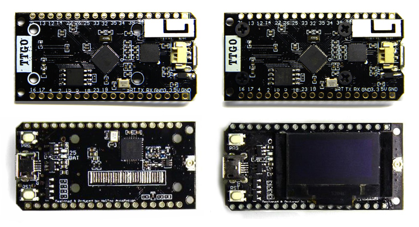
- TTGO LoRa32 v1
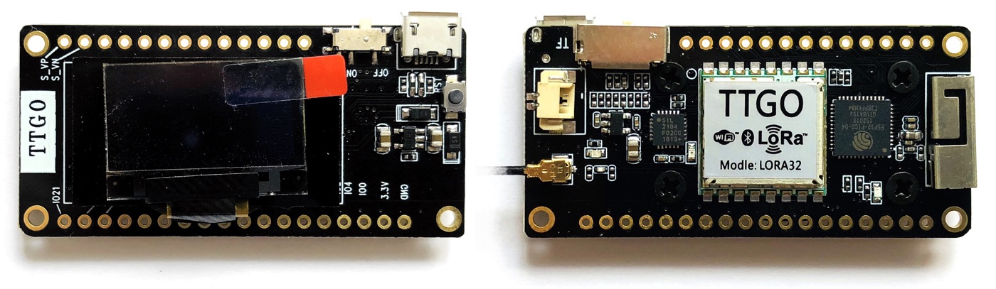
- TTGO LoRa32 v2
- TTGO LoRa32 v2.1
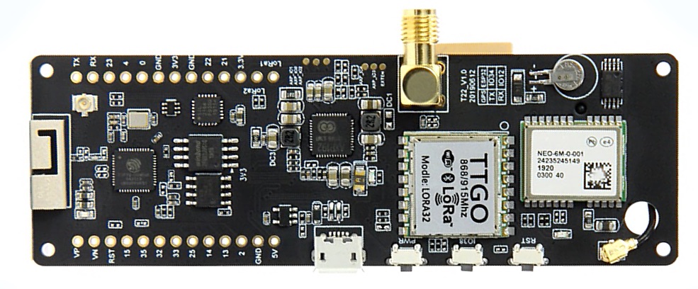
- TTGO T-Beam
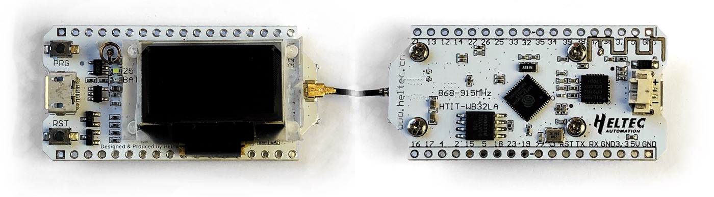
- Heltec LoRa 32
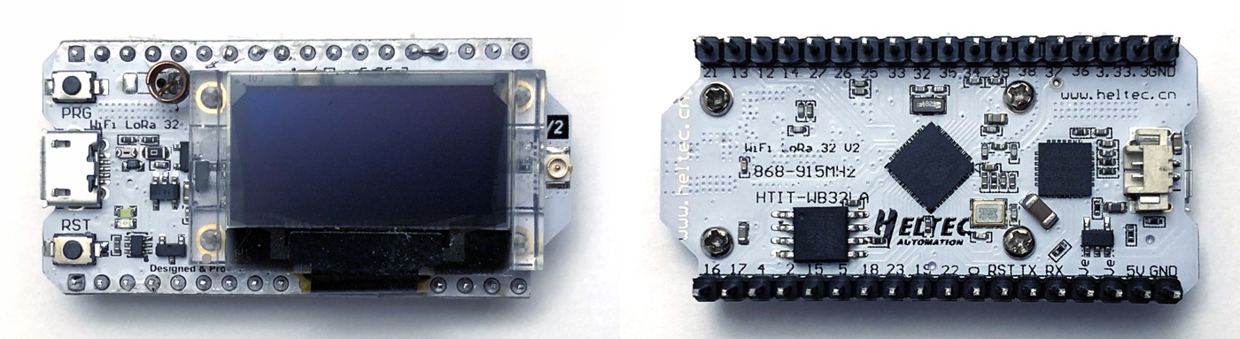
- Heltec LoRa 32 V2
- Adafruit RFM95 breakout board
- Hope RFM95W module
- Wemos D1 R32 / ESPDUINO-32 with Dragino LoRa shield
The pin configuration of each board is shown for each one.
Version 1 boards can be recognized by the metal WiFi antenna along the pins.
Pin configuration
#define TTN_SPI_HOST      HSPI_HOST
#define TTN_SPI_DMA_CHAN  1
#define TTN_PIN_SPI_SCLK  5
#define TTN_PIN_SPI_MOSI  27
#define TTN_PIN_SPI_MISO  19
#define TTN_PIN_NSS       18
#define TTN_PIN_RXTX      TTN_NOT_CONNECTED
#define TTN_PIN_RST       14
#define TTN_PIN_DIO0      26
#define TTN_PIN_DIO1      33
menuconfig
The default TTN values should work fine:
- TTN radio chip: Semtech SX1276 / SX1277 / SX1278 / SX1279
- SPI frequency: 10,000,000 (10 MHz)
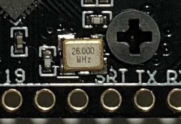
However, these boards usually have a XTAL frequency of 26 MHz (instead of the default 40 MHz). The correct XTAL frequency can be found on the quartz on the back of the board between the pins 19 and SRT (a magnifying glass will be helpful). The XTAL frequency needs to be set with menuconfig at Component config / ESP-32 specific / Main XTAL frequency
Version 2 boards can be recognized by the improved placement of the metal WiFi antenna on the short side of the board while still retaining the tiny U.FL/IPEX connector.
Pin configuration
#define TTN_SPI_HOST      HSPI_HOST
#define TTN_SPI_DMA_CHAN  1
#define TTN_PIN_SPI_SCLK  5
#define TTN_PIN_SPI_MOSI  27
#define TTN_PIN_SPI_MISO  19
#define TTN_PIN_NSS       18
#define TTN_PIN_RXTX      TTN_NOT_CONNECTED
#define TTN_PIN_RST       TTN_NOT_CONNECTED
#define TTN_PIN_DIO0      26
#define TTN_PIN_DIO1      33 †
† DIO1 of SX127x must be manually wired to a free GPIO of the ESP32. Otherwise it will not work. In the above configuration, GPIO 33 has been chosen. See this LilyGO issue for a pinout of the board. DIO1 (labelled LoRa_DIO1) and GPIOs can be found as pin holes (or as pins if pin headers have been soldered) on the long sides of the board.
menuconfig
The default values should work fine:
- TTN radio chip: Semtech SX1276 / SX1277 / SX1278 / SX1279
- SPI frequency: 10,000,000 (10 MHz)
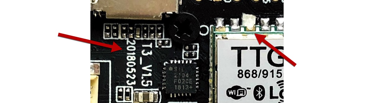
The v2.1 boards can be recognized by the bigger SMA antenna connector (instead of the tiny U.FL/IPEX connector).
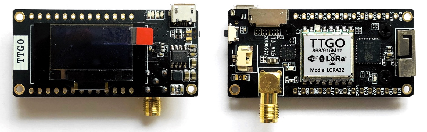
The below information has been verified with a board that was marked: T3_V1.5 20180523. Other versions of the v2.1 boards seem to exist. Also note that the RST pin of the shielded LoRa module (third one from top left) is not connected.
Warning: Version 1.6 boards have a dangerous design flaw. The board is likely to catch fire if the battery is charged while it is connected to the board. Do not charge the battery while connected to the board. See this TTN article for more information.
Pin configuration
#define TTN_SPI_HOST      HSPI_HOST
#define TTN_SPI_DMA_CHAN  1
#define TTN_PIN_SPI_SCLK  5
#define TTN_PIN_SPI_MOSI  27
#define TTN_PIN_SPI_MISO  19
#define TTN_PIN_NSS       18
#define TTN_PIN_RXTX      TTN_NOT_CONNECTED
#define TTN_PIN_RST       TTN_NOT_CONNECTED
#define TTN_PIN_DIO0      26
#define TTN_PIN_DIO1      33
menuconfig
The default values should work fine:
- TTN radio chip: Semtech SX1276 / SX1277 / SX1278 / SX1279
- SPI frequency: 10,000,000 (10 MHz)
Comprehensive board LoRa chip and GPS module.
Pin configuration
#define TTN_SPI_HOST      HSPI_HOST
#define TTN_SPI_DMA_CHAN  1
#define TTN_PIN_SPI_SCLK  5
#define TTN_PIN_SPI_MOSI  27
#define TTN_PIN_SPI_MISO  19
#define TTN_PIN_NSS       18
#define TTN_PIN_RXTX      TTN_NOT_CONNECTED
#define TTN_PIN_RST       23
#define TTN_PIN_DIO0      26
#define TTN_PIN_DIO1      33
menuconfig
The default values should work fine:
- TTN radio chip: Semtech SX1276 / SX1277 / SX1278 / SX1279
- SPI frequency: 10,000,000 (10 MHz)
Pin configuration
#define TTN_SPI_HOST      HSPI_HOST
#define TTN_SPI_DMA_CHAN  1
#define TTN_PIN_SPI_SCLK  5
#define TTN_PIN_SPI_MOSI  27
#define TTN_PIN_SPI_MISO  19
#define TTN_PIN_NSS       18
#define TTN_PIN_RXTX      TTN_NOT_CONNECTED
#define TTN_PIN_RST       14
#define TTN_PIN_DIO0      26
#define TTN_PIN_DIO1      33
menuconfig
The default TTN values should work fine:
- TTN radio chip: Semtech SX1276 / SX1277 / SX1278 / SX1279
- SPI frequency: 10,000,000 (10 MHz)
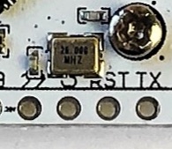
However, these boards usually have a XTAL frequency of 26 MHz (instead of the default 40 MHz). The correct XTAL frequency can be found on the quartz on the back of the board between the pins 22 and RST (a magnifying glass will be helpful). The XTAL frequency needs to be set with menuconfig at Component config / ESP-32 specific / Main XTAL frequency
Pin configuration
#define TTN_SPI_HOST      HSPI_HOST
#define TTN_SPI_DMA_CHAN  1
#define TTN_PIN_SPI_SCLK  5
#define TTN_PIN_SPI_MOSI  27
#define TTN_PIN_SPI_MISO  19
#define TTN_PIN_NSS       18
#define TTN_PIN_RXTX      TTN_NOT_CONNECTED
#define TTN_PIN_RST       14
#define TTN_PIN_DIO0      26
#define TTN_PIN_DIO1      35
menuconfig
The default TTN values should work fine:
- TTN radio chip: Semtech SX1276 / SX1277 / SX1278 / SX1279
- SPI frequency: 10,000,000 (10 MHz)
It's a breakout board with an RFM95W module:
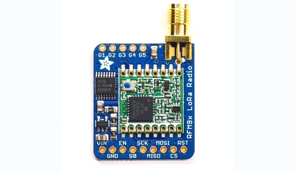
PIN configuration
As the board needs to be wired up, many different pin configurations are possible. This one has been successfully tested:
#define TTN_SPI_HOST      HSPI_HOST
#define TTN_SPI_DMA_CHAN  1
#define TTN_PIN_SPI_SCLK  5
#define TTN_PIN_SPI_MOSI  27
#define TTN_PIN_SPI_MISO  19
#define TTN_PIN_NSS       18
#define TTN_PIN_RXTX      TTN_NOT_CONNECTED
#define TTN_PIN_RST       14
#define TTN_PIN_DIO0      26
#define TTN_PIN_DIO1      33
menuconfig
The default TTN values should work fine:
- TTN radio chip: Semtech SX1276 / SX1277 / SX1278 / SX1279
- SPI frequency: 10,000,000 (10 MHz)
It's an inexpensive module for the SX1276 chip.
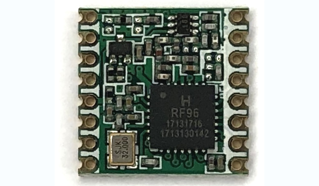
PIN configuration
As the module needs to be wired up, different pin configurations are possible. This one has been successfully tested:
#define TTN_SPI_HOST      HSPI_HOST
#define TTN_SPI_DMA_CHAN  1
#define TTN_PIN_SPI_SCLK  5
#define TTN_PIN_SPI_MOSI  27
#define TTN_PIN_SPI_MISO  19
#define TTN_PIN_NSS       18
#define TTN_PIN_RXTX      TTN_NOT_CONNECTED
#define TTN_PIN_RST       14
#define TTN_PIN_DIO0      26
#define TTN_PIN_DIO1      33
Don't forget to connect some sort of antenna. A wire of half the wave length (17.2 cm for 868 MHz) works fine.
menuconfig
The default TTN values should work fine:
- TTN radio chip: Semtech SX1276 / SX1277 / SX1278 / SX1279
- SPI frequency: 10,000,000 (10 MHz)
The Wemos D1 R32 and ESPDUINO-32 are ESP-32 based boards in the format of an Arduino. Therefore, they can be used with Arduino shield and in particular with the Dragino LoRa shield:
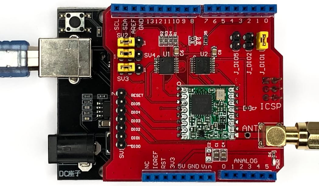
PIN configuration
#define TTN_SPI_HOST      VSPI_HOST
#define TTN_SPI_DMA_CHAN  1
#define TTN_PIN_SPI_SCLK  18
#define TTN_PIN_SPI_MOSI  23
#define TTN_PIN_SPI_MISO  19
#define TTN_PIN_NSS       5
#define TTN_PIN_RXTX      TTN_NOT_CONNECTED
#define TTN_PIN_RST       13
#define TTN_PIN_DIO0      26
#define TTN_PIN_DIO1      27
Additionally, configure the jumpers on the shield as shown in the above image.
menuconfig
For the reset pin, a special configuration is needed:
- TTN radio chip: Semtech SX1276 / SX1277 / SX1278 / SX1279
- SPI frequency: 10,000,000 (10 MHz)
- Reset states (Toggle between low and high)