Removing boundary artifacts #567
Comments
|
sorry for the late reply - if i guess correctly the 2 parts of the mesh have some large overlapping... you can remove it by cutting both with a horizontal plane ( |
No worries.
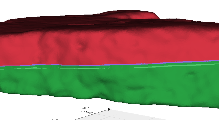
Indeed this is the case, this is due to the fact that the two scanned outputs are not perfectly precise. So if you see here: There is always some kind of overlapping either from one or the other (notice that sometimes the green is above red and vice versa), this also causes some kind of self intersecting faces problem where when the to surfaces are not perfect aligned I get some kind of artificial "bubbles" from the two overlapped surfaces. Thus, I am not sure that just cutting with a horizontal plane would work. In principle I would get the same result as with trimming the boundaries. An idea to address the "bubble" issue would be to solidify the mesh by filling it in so that I do not have any hollow inner parts anymore but then still on the boundaries I would have these parts extending out of the main core of the mesh. These parts I would like to trim out.
Can you elaborate a bit more on these, in practice I would like to get a watertight mesh (I am planning to 3D print the pieces) but more important is to manage to get a final mesh with as much as possible less artifacts on the alignment. From my experience transforming a non-watertight mesh to a watertight one is quite easy once you have a well reconstructed mesh. |

|
I had a try with it: import vedo as vd
import numpy as np
m1 = vd.Mesh("frag_3_final_dec.ply").c("green4").alpha(1)
m2 = vd.Mesh("frag_3__final_dec.ply").c("red4").alpha(1)
# m1.decimate(0.1).write('frag_3_final_dec.ply')
# m2.decimate(0.1).write('frag_3__final_dec.ply')
T = np.array([[-0.9969830354, -0.0742881466, -0.0224966296, 202.4966262662],
[0.0534353633, -0.4466713800, -0.8931009687, 363.3441404664],
[0.0562982151, -0.8916086303, 0.4492934024, 228.7605892738],
[0.0000000000, 0.0000000000, 0.0000000000, 1.0000000000]])
m3 = m1.clone()
m4 = m2.clone().applyTransform(T, reset=True)
a=60
m3.RotateX(a)
m4.RotateX(a)
m3.cutWithPlane((0,0,205),'-z')
m4.cutWithPlane((0,0,206),'z')
b3 = m3.boundaries().extractLargestRegion().c('green6')
b4 = m4.boundaries().extractLargestRegion().c('purple6')
pts3 = m3.points()
pts4 = m4.points()
pcl3 = vd.Points(pts3)
pcl4 = vd.Points(pts4)
lines=[]
pb = vd.ProgressBar(0, b3.NPoints())
for p in b3.points():
pb.print()
idx3 = pcl3.closestPoint(p, returnPointId=True)
idx4 = pcl4.closestPoint(p, returnPointId=True)
lines.append([pts3[idx3], pts4[idx4]])
pts3[idx3] = pts4[idx4]
m3.points(pts3) # update mesh vertices to seal the gap
m = vd.merge(m3,m4).clean().c('indigo5')
lns = vd.Lines(lines, lw=2)
vd.show(m3, m4, b3, b4, lns, axes=1)
vd.show(m, b3, b4, axes=1).close()
you'll need to uncomment the two |

|
Thanks Marco, I had a look on your solution I also played a bit with different options but I didn't like the output that much, it seems that I am still getting some artifacts where the connection between the two parts are. However, while I was trying to understand your code I got another idea for which I would need your opinion and possibly your help. If I load the initial merged mesh and extract the boundaries as you can see it gives me the points that are extending from the main body of the mesh: Now since I have this points I can iterate though and delete them, however as you can see at some point some of the points go in the inner side thus what I wanted to do is that once a point is in the inner part of the mesh to exclude it from deletion (see in the image above the bottom part of the mesh where the red line is not visible anymore). However, I am not sure how to define whether a boundary point is in the outer or inner side of the mesh. Any idea how to define inner and outer boundary points? |

|
There is a method called Another idea could be to still cut with the plane to remove each side of the 2 meshes but then just forget about all faces and recreate the surface with |
Indeed, this didn't work plus it was quite slow.
Finally I found another solution, which seems to work quite nicely, by using the poisson reconstruction filter from pymeshlab: as you can see it seems to do quite some nice job. And here is the code snippet for the reference: In any case, thanks a lot again @marcomusy. Your help is always valuable. |


|
Looks great ! Are you sure the result from the screened poisson is still manifold in the general case of overlapping point clouds? import vedo as vd
import numpy as np
m1 = vd.Mesh("frag_3_final.ply").c("green4")
m2 = vd.Mesh("frag_3__final.ply").c("red4")
T = np.array([[-0.9969830354, -0.0742881466, -0.0224966296, 202.4966262662],
[0.0534353633, -0.4466713800, -0.8931009687, 363.3441404664],
[0.0562982151, -0.8916086303, 0.4492934024, 228.7605892738],
[0.0000000000, 0.0000000000, 0.0000000000, 1.0000000000]])
m3 = m1.clone()
m4 = m2.clone().applyTransform(T, reset=True)
m3.rotateX(60).cutWithPlane((0,0,206),'-z')
m4.rotateX(60).cutWithPlane((0,0,206),'z')
m = vd.merge(m3,m4).clean()
mr = vd.recoSurface(m, dims=(100,100,30), radius=3).smooth()
vd.show([[m3, m4], mr], N=2, axes=1).close()
at a first look the meshlab reconstruction looks better than the vtk one. |

|
As far as I understood, by checking on the manual, as well on some videos the result should be manifold (also checking on some of the output files they seem to be). For the overlapping regions the parameters that I used seem to do the trick for most of my models. Thus, I would stick with that and actually in the cases that it fails is due the bad retrieved sub-meshes. Yes, I noticed that the result from the meshlab lib is (or looks at least) quite good. |
Hi @marcomusy,
I have two sub-meshes, bottom and upper parts scanned with a 3d scanner, of a complete mesh which I then register in order to get this complete mesh:
Though the extracted transformation seems to work quite good, if you notice I am getting this kind of artifacts in the boundaries where it seems that the overlapping between the two sub-meshes is not perfect. I've tried to apply a smoothing filter but it didn't really help much thus I wanted to ask you if you have anything in mind that might help to get rid of or decrease the effect of these artifacts.
My initial idea was to trim the boundaries before the registration as discussed here but I still get some of them around the edges:

frag_3a.ply.zip
The text was updated successfully, but these errors were encountered: