Data Protocol
 doc/images/0220517153950.png
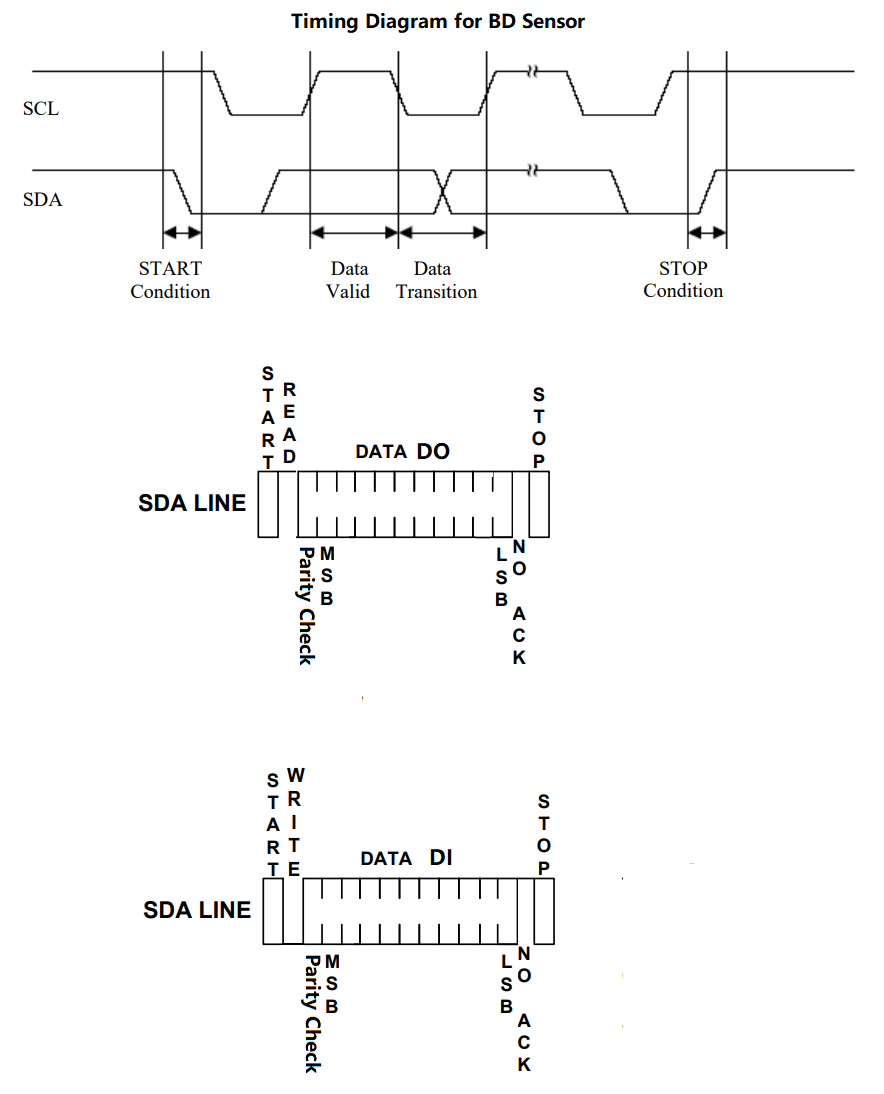
This is not a standard I2C, the protocol of standard I2C has address transfer in the timing diagram but this sensor has not. the reason for that is we need to get quick response from the sensor when homing z axis in 3D printer. Here is a SoftwareI2C library for this sensor, with this library we can connect this sensor to any 2 gpio pins on any MCU.
doc/images/0220517153950.png
This is not a standard I2C, the protocol of standard I2C has address transfer in the timing diagram but this sensor has not. the reason for that is we need to get quick response from the sensor when homing z axis in 3D printer. Here is a SoftwareI2C library for this sensor, with this library we can connect this sensor to any 2 gpio pins on any MCU.
DATA DO: data output from sensor,10bit,range: 0 to 1023,1 represent 0.01mm(e.g. 46 means the measure distance is 0.46mm).
DATA DI : data input,10bit,range: 0 to 1023, 1 represent 0.1mm, (0 1 ... 39 represent 0mm 0.1mm ... 3.9mm)
data input >=1016 will be recognized as command, for example:
#define CMD_READ_VERSION  1016               // read sensor version
#define CMD_START_READ_CALIBRATE_DATA   1017 // start reading raw calibration data
#define CMD_DISTANCE_MODE             1018   // finish reading raw calibration data
#define CMD_START_CALIBRATE 1019             // start calibration
#define CMD_DISTANCD_RAWDATA_TYPE 1020       // switch output distance data type to raw data, default is mm (1 represent 0.01mm)
#define CMD_END_CALIBRATE 1021               // finish calibration
#define CMD_REBOOT_SENSOR 1022               // BDsensor will reboot itself
#define CMD_SWITCH_SENSOR 1023               // BDsensor will work as normal inductive probe like a switch sensor.
Following is the reading version process
-
Send command CMD_READ_VERSION
BD_i2c_write(CMD_READ_VERSION); -
Read first byte of version text string(20 bytes)
BD_i2c_read()&0x3ff; -
Read second byte of version text string
BD_i2c_read()&0x3ff; -
Read 3rd byte of version text string
BD_i2c_read()&0x3ff;
........ -
Read 20th byte of version text string
BD_i2c_read()&0x3ff; -
Send command CMD_END_READ_CALIBRATE_DATA
BD_i2c_write(CMD_END_READ_CALIBRATE_DATA);
Send gcode command M102 S-6 to read sensor version.
Following is the Calibration steps process
-
Send command CMD_START_CALIBRATE
BD_i2c_write(CMD_START_CALIBRATE); -
Move the bed distance sensor to the 0 mm postion(e.g. send gcode G1 Z0 to 3D printer and wait it reach the position),then send data 0 to sensor
BD_i2c_write(0);the sensor will remember this position as the 0 position. -
Move the bed distance sensor to the 0.1 mm postion,then send data 1 to sensor
BD_i2c_write(1); -
Move the bed distance sensor to the 0.2 mm postion,then send data 2 to sensor
BD_i2c_write(2); -
Move the bed distance sensor to the 0.3 mm postion,then send data 3 to sensor
BD_i2c_write(3);
........ -
Move the bed distance sensor to the 3.9 mm postion,then send data 39 to sensor
BD_i2c_write(39); -
Send command CMD_END_CALIBRATE
BD_i2c_write(CMD_END_CALIBRATE);the sensor will store above 40 calibration data.
Source code in marlin firmware:
Send gcode command M102 S-5 to read sensor version.
Following is the reading Calibration raw data steps
-
Send command CMD_START_READ_CALIBRATE_DATA
BD_i2c_write(CMD_START_READ_CALIBRATE_DATA); -
Read first calibration raw data
BD_i2c_read()&0x3ff; -
Read second calibration raw data
BD_i2c_read()&0x3ff; -
Read 3rd calibration raw data
BD_i2c_read()&0x3ff;
........ -
Read 40th calibration raw data
BD_i2c_read()&0x3ff; -
Send command CMD_END_READ_CALIBRATE_DATA
BD_i2c_write(CMD_END_READ_CALIBRATE_DATA);
Source code in marlin firmware:
Send gcode command :
M102 Sx // Set the adjustable Z height value, value x is from 0 to 39, e.g. M102 S4 means it will do adjusting while the Z height <=0.4mm , disable it by M102 S0.
How it works:
Read the current z value from BDsensor and compare it to software setting z value and adjust it with Baby Step function(BABYSTEPPING) in marlin firmware
Source code in marlin firmware:
How it works:
If the Z current value reading from BDsensor is below 0.01mm then set the endstop pin value to one else zero.
Source code in marlin firmware:
endstops.bdp_state_update(z_sensor <= 0.01f); it's in Marlin/src/feature/bedlevel/bdl/bdl.cpp
static void bdp_state_update(const bool z_state) { bdp_state = z_state; }it's in Marlin/src/module/endstops.h
#define READ_ENDSTOP(P) ((P == Z_MIN_PIN) ? bdp_state : READ(P)) it's in Marlin/src/module/endstops.cpp
here is a simple arduino testing code. It read the distance data from BDsensor after initial the communication port.
void setup() {
  delay(500);
  // init the communication port.
  BD_SENSOR_I2C.i2c_init(I2C_BED_SDA,I2C_BED_SCL,0x3C,10);
  Serial.begin(115200);
}

void loop() {
    unsigned short read_data=0;
    //read distance from BDsensor
    read_data=BD_SENSOR_I2C.BD_i2c_read();
    if(BD_SENSOR_I2C.BD_Check_OddEven(read_data)==0)
      printf("Data Check error!\n");
    else
    {
      Distance=(read_data&0x3ff)/100.0;
      //display the Distance
      sprintf(tmp_1,"Distance:%.2f mm\n",Distance);
      printf(tmp_1);
    }
    delay(100);
}