The current Arduino library has bugs in the freelist implementation, which can lead to difficult to debug system hangs. For maximum reliability of my home automation projects, I built an external hardware watchdog.
The purpose of a watchdog is to decide when things have gone wrong by listening for a heartbeat signal which is only sent under good conditions. If something goes so wrong that the program cannot recover from it, or cannot recover in time, the watchdog timer's job is to reset things to a known good state. In embedded systems, this often happens by simply resetting to the initial state.
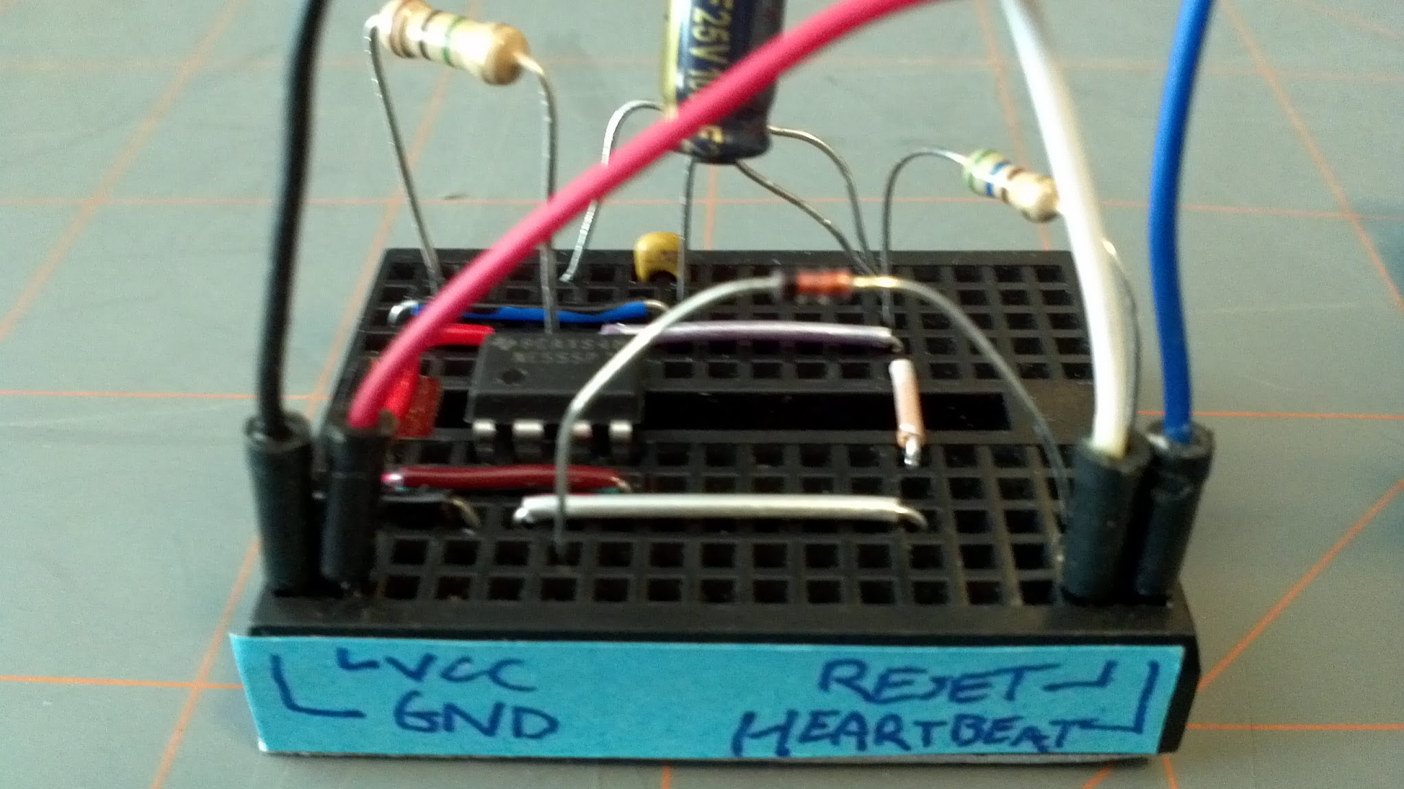
Connect +5V and GND from the Arduino to the watchdog circuit's +5V and GND pins. Connect the watchdog circuit's output line to the Arduino's reset pin, and watchdog circuit's input line to one of the digital I/O pins for the Arduino.
Configure the digital I/O pin to be normally high-Z ("INPUT"). Periodically connect it to GND ("OUTPUT", "LOW") and hold for a few hundred milliseconds to send the heartbeat signal.
If the heartbeat signal is not sent within approximately 120 seconds of the last heartbeat signal (with documented R and C values; changing values will change timing), the Arduino's reset line will be held low, causing system reset.
- https://raw.github.com/mattbornski/Arduino-Watchdog-Circuit/master/arduino-555-watchdog-circuit.png
- https://www.circuitlab.com/circuit/cc9d7s/arduino-555-watchdog-circuit/
See also:
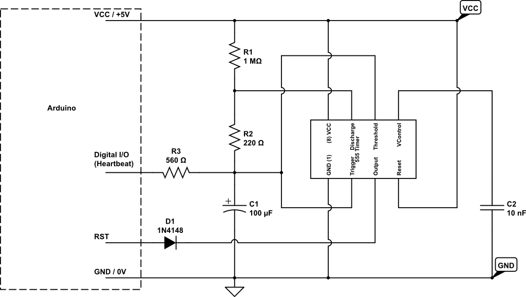
The Arduino's reset pin is active low; therefore, in order to trigger a reset we will hold the pin low for a period of time. The 555's output pin will be used for this purpose; it is connected to the Arduino's reset pin through a diode to ensure that no stray signals on the Arduino's reset line can cause unexpected interference in the 555.
Under normal operation, charge builds up in C1 while the 555's output pin is set high. When C1's charge is sufficient to reach the 555's threshold (approximately 2/3 of VCC), the 555 output will flip low. Since the 555's output is tied to the Arduino's reset line, this will reset the system.
When the Arduino sends a heartbeat to the watchdog circuit, the heartbeat line is set to a low output, aka GND. This drains charge from C1 through R3, which in turn means that C1 is further away from the 555's threshold voltage.
The main components of this circuit are the 555 timer, C1, R1, and R2. Changing the values of C1, R1, and R2 will change the charging/discharging times, and can be useful if you want a circuit with a different time profile. D1, C2 and R3 are mostly about guarding against voltage fluctuations and current surges that can damage your equipment and cause transient resets or failures.