Automatic Bed Leveling Issues
Ender 3 S1 users frequently find that their first layer does not stick properly to their bed, despite their best efforts tramming the bed and invoking the Automatic Bed Leveling (ABL) capabilities of their S1.
A quick search of the web then leads them to find many fellow S1 users with the same problem: the ABL does not work!
This wiki page aims to collect as much information as possible on the following issues:
- Your first layer does not seem to stick to the print bed, in particular in the front or in the back of the bed
- The Z offset changes randomly from print to print. One print will come out perfect, the next print will have the nozzle too close to the bed.
Our goal with this wiki:
- Document the various issues observed with ABL on the Ender 3 S1 and its variants
- Document (possible) solutions that may help inexperienced and experienced users alike
- Collect data to understand patterns and root causes
In particular, the data collected here is intended as input for the experts to understand the problem and come up with a fix.
Issues that are not relevant here:
- Your ABL probing process does not start or it stops in the middle
Everyone is welcome to contribute their findings, thoughts and experiments to this wiki! All you need is an account on Github.com
This wiki is borne out of discussions on the awesome Ender 3 discord server. We're happy to see you join us there.
First things first: ABL is not a replacement for bed tramming!
Your printer has four wheels on its print bed. Use the wheels to make sure the print bed is as level as possible before performing using ABL. While ABL can compensate for some tilting of your print bed, there is no reason to make it work harder than necessary. The real strength of the ABL is in compensating for unevenness of your print bed.
While you do the bed tramming using the four wheels, steer clear of any bed tramming wizards using the CRTouch probe. After all, you are here because you may be having problems with the CRTouch probe. Just do it manually.
After you have trammed the bed, you need to tweak the Z offset. The Z offset is the difference in distance between your CRTouch probe hitting the bed and your nozzle hitting the bed. Your printer is using the CRTouch probe as a Z axis endstop: Z=0 is the position where the CRTouch probe touches the bed. Your nozzle needs to go just a little bit lower; that's the Z offset.
The Automatic Bed Leveling (ABL) on the S1 works as follows:
- The printer moves the CRTouch probe across the print bed to pre-defined points (4x4 on the stock firmware)
- At each point, the probe is deployed and the distance to the bed is measured
- The result of this process is a mesh: like a topology map, this describes the valleys and bumps on your printer's bed.
- The printer applies this mesh during the first layers by moving the Z axis (and thus the nozzle) closer to the bed or away from the bed
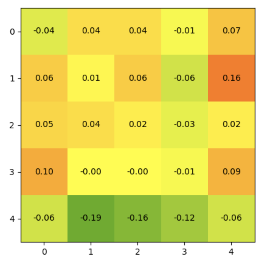
This is an example of a 5x5 mesh:
-0.09	-0.09	-0.07	0.02	0.05
0.10	0.05	0.00	0.04	0.04
0.04	0.03	-0.03	0.04	0.06
-0.02	-0.06	-0.11	-0.04	-0.02
-0.02	-0.09	-0.18	-0.13	-0.14
When visualized, the mesh looks like this:
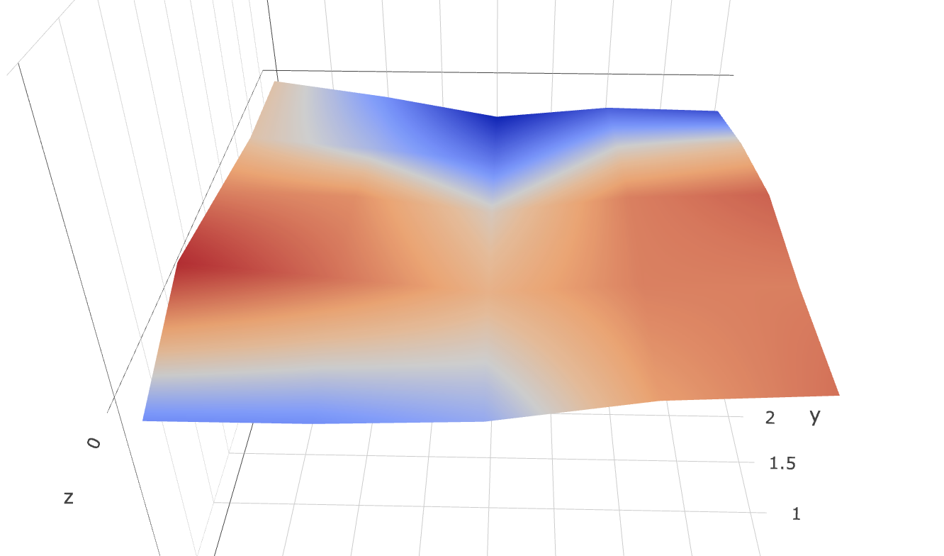
A different visualization of the same mesh:
The matrix only consists of specific points. To determine how to adjust the Z axis movements between points, the printer firmware is applying an interpolation algorithm. This is a simple linear interpolation: half-way between offsets 0.1 and 0.2, the printer will apply a 0.15 offset. Details of the UBL implementations
Once a mesh for your particular bed exists, you need to ensure that the mesh is applied. Use the M420 S1 gcode to enable the compensation.
To sum up this section, Automatic Bed Leveling is a two-step process:
- Generate the mesh by running the bed probing
- Enable Z axis compensation based on the mesh for your prints
Instead of using the CRTouch probe to generate the mesh, it is possible to generate the mesh manually:
- Generating the mesh from scratch without the CRTouch probe
- Note that the link above points to the Marlin UBL implementation; other implementations may differ
- Editing a previously probed mesh
This document is concerned with making Automatic Bed Leveling work; i.e. using the CRTouch probe.
Depending on your firmware, different ABL implementations are used.
- Both Creality stock (source) and MRiscoC (source) use Bilinear Leveling
- MRiscoC UBL variants use UBL
The causes and fixes for my "I ran the ABL and my first layer does not stick" on the S1 are manifold. Some are mechanical while others may be found in software.
You can work through the following list and see if any of the issues applies to you. If a fix works to you, please let us know on the discord or add a comment here.
If your printer is out of true or you have loose wheels, you need to fix this first.
This video is a good start:

Clean your printer's bed.
Your Z axis has two steppers which are connected to a single driver. It is possible that one of the steppers, or rather one of the Z axis lead screws, is offset compared to the other. While this issue should be compensated by the ABL, it is a reasonable thing to check.
- Measure distance between the X axis extrusion and the base of the printer
- Possible indication: If your bed mesh shows that left/right side of the bed is higher than the other
- TODO: Insert Video
If your probe is broken and does not give repeatable results, the resulting mesh will not be useful.
- Use the Marlin Probe Repeatability test (M48) or invoke the test from your printer's LCD (on MRiscoC firmware)
- For the CRTouch, the results should be better than TODO
- Check mechanics of your printer
- Check that CRTouch probe is mounted correctly and that the screws are not tight
- CRTouch uses an optical sensor: try turning off light sources around the printer and see if results improve
- Some reports on the net (not necessarily for the S1) indicate that using wires with better shielding (e.g. CAT5) has improved results
- Replace the sensor - possibly under warranty
The Y axis comes bent from the factory on many printers. This is due to overtightening of the four bolts that fix the Y axis extrusion to the chassis during factory assembly.
First approach:
- Turn off printer
- Ensure Y axis wheels are tightened correctly
- Ensure your wheels do not have any flat spots
- TODO: loosen and retighten screws?
- Gently roll the bed from front and back multiple times with your hand
- Feel for any bumps or sticky points when moving the bed
TODO: There was a good reddit comment explaining the approach. Add link.
Second approach:
- Remove Y axis extrusion Y 1.1 Remove bed from from Y axis extrusion 1.2 Remove 6 screws holding the Y axis extrusion 1.3. Remove Y axis stepper motor
- Put Y axis on flat surface and check if it is level 3.1. Put a strong light behind the extrusion and check if a bright spot appears where the extrusion meets the flat surface
- Check the grooves for the wheels 4.1 Feel with your fingers (or measure with a set of calipers) if the grooves where the wheels are riding have no bumps
If your Y axis is bent or damaged, you have the following options.
- Get a new Y axis 1.1 Creality currently does not sell these (as of 2022-11) 1.1 However, Creality support will send you a new extrusion (warranty)
See below.
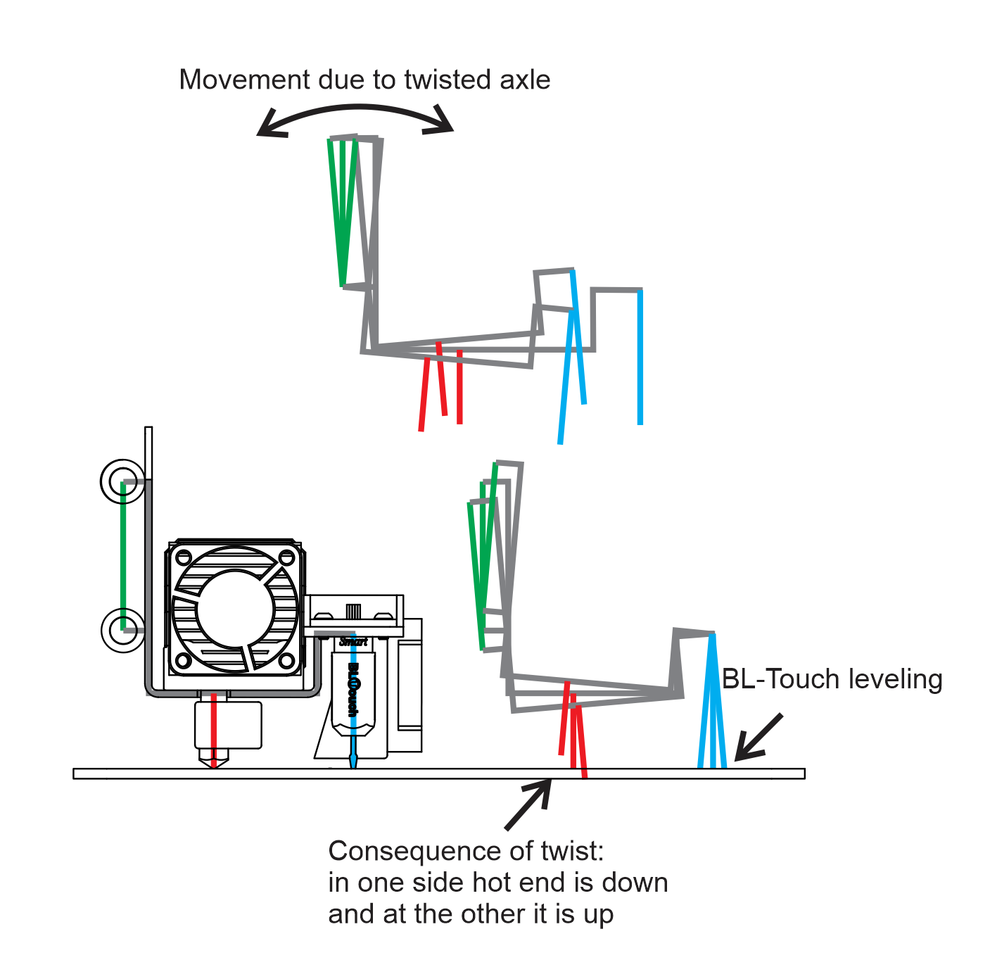
If your X axis is twisted in itself, the probe will have a different Z offset as the probe moves along the X axis.
@MauroGil66 has created this diagram to illustrate the problem:
TODO!
- If you see a systematic pattern that the right or left side of the bed is higher/lower than the other?
- Straightening the X axis to remove the warp 1.1 Shimming (TODO: video?)
- Apply software compensation via Marlin's M423 gcode 2.1 Recent Marlin versions add support for X_AXIS_TWIST_COMPENSATION 2.1.1 This needs to be enabled in your firmware build. Currently NOT enabled in MRiscoC firmware. 2.1.2 Once enabled, the Marlin [M423 gcode|https://marlinfw.org/docs/gcode/M423.html] or the LCD can be used to adjust the compensation 2.1.3 See feature PR and feature request for additional information 2.1.4 TODO: this fix is not verified.
- Use a Y=0 offset probe mount (see below)
Your bed may be out of true so much that the ABL cannot compensate for it.
- TODO
- Shimming
- Get replacement bed
- Increase mesh density
- TODO
The bed mount itself may be warped. However, this should not cause too much trouble - the ABL should be able to compensate for that given that the error will be constant across the range of motion of the bed.
TODO
TODO
The CRTouch probe is offset from the nozzle. While the nozzle can reach the entire bed, the probe cannot!
TODO: find out default mesh inset
- Are your first layer problems located in an area of the bed where the probe does not reach?
- TODO: document the mesh inset and describe where this problem could be expected
The general approach to fixing is to increase the size of the mesh. This involves the following:
- Telling the printer how far it can move the X/Y axis without hitting something
- Adjusting the bed size to the maximum (TODO: required)
- Adjusting the mesh inset to the maximum
X axis:
- The X axis can move sufficiently far to the right to ensure good probe coverage on the right side of the bed
- This needs to be enabled:
- Setting the maximum X axis movement to XXX (TODO - 245 for mhaas)
- Setting the maximum bed size to 235 (Valdus - is it necessary?)
- Adjust the mesh inset size (requires MRiscoC firmware or similar)
Y Axis:
-
The probe cannot reach the back portion of the bed:
- The probe sits in front of the nozzle
- The bed cannot move back far enough to get the probe to the edge of the bed
- To address this:
- Get a Y=0 offset probe mount (see below)
- Subsequently adjusting the mesh inset (requires MRiscoC firmware or similar)
-
The probe cannot reach the front portion of the bed:
- TODO: is this an issue with the stock mount? Is this an issue with Y=0 offset mount?
- If this is an issue: can be addressed by:
- Adjusting bed size and/or max Y axis reach
- Subsequently adjusting the mesh inset
Moving your CRTouch probe in line with the nozzle helps with a few things:
- Reduce impact of bent Y rail or warped X axis on the resulting mesh
- Increase mesh size to cover more of the bed with the mesh.
To implement this fix, do the following:
- Print a Y=0 offset probe mount
- This model is a good start
- Printing in PLA is OK for testing. For long-term reliability, use a filament with better temperature stability, like PETG or ABS
- Mount it on your printer
- Determine the new relationship between probe and nozzle. This is called the XZ offset: how far away from your nozzle is the probe now? Ideally, the Y offset is now 0 or close to 0, but the X offset is still there.
- See this video to determine your X and Y offsets
- Apply your X and Y offsets to your firmware.
- In the MRiscoC firmware, you can use the LCD or the M851 gcode
- Run ABL again to create a new mesh
- Make sure to readjust your Z offset as well
NB: With the new mount linked above, my (mhaas) Y offset is not 0, but rather 1.2mm.
Even with all the mechanical points addressed, ABL may still fail to provide a solid first layer.
There is some evidence that some instances of the ABL issue are indeed caused by software.
First, some users find that using the Klipper firmware solves their ABL problems completely. Note that this is not the case for all users.
Second, some software settings have a marked impact on the mesh: different settings produce different meshes!
The Marlin firmware offers several settings related to the CRTouch probe:
- Highspeed (HS) Mode
- Multiple Probing (MP)
- Probe Feed Speed
Additionally, there are reports that setting the Z offset to 0 produces completely different meshes than having a non-0 Z offset. See issue #195 in the MRiscoC firmware repository. The main finding in issue #195 is that disabling MULTIPLE_PROBING will produce a correct mesh regardless of the value of the Z offset.
I (mhaas) did several experiments on different combinations of Z offset, HS mode and muliple probing and I can confirm that multiple probing has the biggest impact on the resulting mesh out of these.
Consider the following diagram (Z offset=0, HS mode on, Multiple Probing on and off):
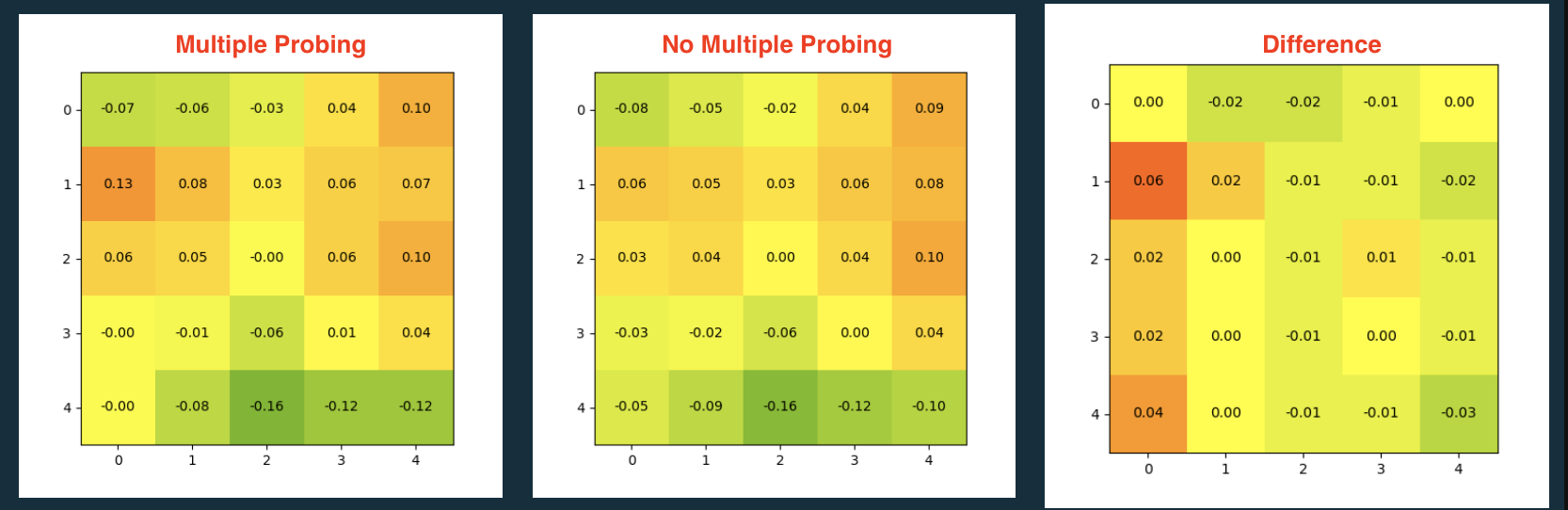
I ran experiments with different settings and then compared the meshes to understand which setting has the biggest impact. You can see the full set of experiments here. Beyond MP, varying the Z offset and MP will also have an impact.
I have not yet concluded my analyis of the existing data and execution of additional experiments. However, one question emerges: why would Multiple Probing lead to vastly different meshes if the CRTouch probe passes the M48 Probe Repeatability Test?
The math to process the multiple probes is a very simple averaging operation implemented in a few lines of code. Where does it go wrong? Sadly, this code is closed source in MRiscoC's firmware.
To move forward with this investigation:
- Run stock Marlin and enable verbose mode and perhaps add additional debug prints to get further insights into the computation happening here.
TODO: further describe what HS mode does.
Earlier S1 models shipped with a STM32 F1 MCU (TODO: add full name). These models seem to be mostly unaffected by ABL issues.
Newer S1 models are now shipping with a STM32 F4 MCU. These models seem to be more prone to ABL issues. But do note that not all F4 boards are affected!
One salient difference between F1 and F4 MCUs is the presence of a FPU in the F4. A bug in the FPU might explain the problems; see also the early Pentium CPUs which were affected by an FPU bug.
To move forward with this hypothesis: can we compile the F4 firmware with a soft FPU implementation?
- Stock Marlin firmware sets Z_PROBE_FEEDRATE_FAST to 4*60 mm/min and the Z DEFAULT_MAX_FEEDRATE to 5mm/s
- Stock Creality firmware sets Z_PROBE_FEEDRATE_FAST to 8*60 and Z DEFAULT_MAX_FEEDRATE to 5mm/s
- MRiscoC firmware sets Z_PROBE_FEEDRATE_FAST to 16*60 and a Z DEFAULT_MAX_FEEDRATE to 20mm/s
The Z_PROBE_FEEDRATE_SLOW is defined as Z_PROBE_FEEDRATE_FAST / 2.
In case of MRiscoC, the Z_PROBE_FEEDRATE_ is much higher than Marlin or Creality.
The idea of the Z_PROBE_FEEDRATE hypothesis is that the high Z speed influences the results of the probe. This effect does not appear when the M48 probe reliability test is used. Different code paths are used here. The mesh probing code calls Probe::run_z_probe which internally adjusts the Z axis at Z_PROBE_FEEDRATE_FAST or Z_PROBE_FEEDRATE_SLOW when executing multiple probes:
do_blocking_move_to_z(current_position.z + Z_CLEARANCE_BETWEEN_PROBES, z_probe_fast_mm_s);
The M48 code, on the other hand, does not adjust the Z axis and calls the lower-level Probe::probe_at_point method.
This would explain why disabling MULTIPLE_PROBING changes the mesh drastically.
To understand the impact of the Z speed, we can get the individual probing results (before averaging) by compiling the firmware with #define DEBUG_LEVELING_FEATURE and sending the M111 32 gcode.
With the debug facilities in place, we run the mesh probing several times for different Z axis speeds (e.g. 601m/min, 604m/min, 60*16m(min). Grab the serial logs sent by the printer (e.g. by enabling serial logging in Octoprint) for analysis.
With higher Z speeds, I expect that the variance between individual probe results will be higher.
TODO: Does the the CRTouch probe in Highspeed mode cause additional travel due to Z_CLEARANCE_BETWEEN_PROBES? Or is the same for HS on/off? TODO: Is Z_PROBE_FEEDRATE_FAST only used for Multiple Probing? Or also for Single Probing (as opposed to Z_PROBE_FEEDRATE_SLOW)
Links:
- For the Klipper firmware, issue #5750 states that Z speed has an impact on precision.
- Note: this does not mean that Marlin is affected by the same issue.
Issue #13758 on Marlin reports that insufficient power supply to the probe can also result in a bad mesh being generated.
In this report, mostly the outer area of the bed is affected. In these areas, the M48 probe repeatability test failed.
The cause in this were thin wires which led to a voltage drop when the sensor was consuming 100mA during the probe. Using a separate power supply for the probe fixed the problem in this case.
You may be affected by this issue if:
- Your M48 test fails in the areas where your first layer does not stick
How to fix:
- Improve wiring
Electromagnetic interference may cause the probe to return inaccurate results.
Given that the CRTouch generally works fine on the Ender 3 V2 and can be problematic on the S1, the question arises: what are the relevant differences between the V2 and S1? One of the biggest differences is the extruder, which is a completely different design. In particular, the wiring is different: a single ribbon cable is used to transfer both power (including noisy stepper input!) and signal.
The Marlin firmware recognizes the EMI problem and provides options to turn off heaters, fans and steppers during the probe. These settings are intended to decrease EMI and increase probe stability (code taken from stock Marlin):
/**
 * Enable one or more of the following if probing seems unreliable.
 * Heaters and/or fans can be disabled during probing to minimize electrical
 * noise. A delay can also be added to allow noise and vibration to settle.
 * These options are most useful for the BLTouch probe, but may also improve
 * readings with inductive probes and piezo sensors.
 */
//#define PROBING_HEATERS_OFF       // Turn heaters off when probing
#if ENABLED(PROBING_HEATERS_OFF)
  //#define WAIT_FOR_BED_HEATER     // Wait for bed to heat back up between probes (to improve accuracy)
  //#define WAIT_FOR_HOTEND         // Wait for hotend to heat back up between probes (to improve accuracy & prevent cold extrude)
#endif
#define PROBING_FANS_OFF            // Turn fans off when probing
//#define PROBING_ESTEPPERS_OFF     // Turn all extruder steppers off when probing
//#define PROBING_STEPPERS_OFF      // Turn all steppers off (unless needed to hold position) when probing (including extruders)
#define DELAY_BEFORE_PROBING 200    // (ms) To prevent vibrations from triggering piezo sensors

// Require minimum nozzle and/or bed temperature for probing
//#define PREHEAT_BEFORE_PROBING
#if ENABLED(PREHEAT_BEFORE_PROBING)
  #define PROBING_NOZZLE_TEMP 120   // (°C) Only applies to E0 at this time
  #define PROBING_BED_TEMP     50
#endif
MRiscoC already applies some of these options:
#define PROBING_HEATERS_OFF       // Turn heaters off when probing  // MRiscoC Probe stability
#if ENABLED(PROBING_HEATERS_OFF)
  //#define WAIT_FOR_BED_HEATER     // Wait for bed to heat back up between probes (to improve accuracy)
  //#define WAIT_FOR_HOTEND         // Wait for hotend to heat back up between probes (to improve accuracy & prevent cold extrude)
#endif
#define PROBING_FANS_OFF          // Turn fans off when probing  // MRiscoC Turn fans off for avoid vibrations and interference
//#define PROBING_ESTEPPERS_OFF     // Turn all extruder steppers off when probing
//#define PROBING_STEPPERS_OFF      // Turn all steppers off (unless needed to hold position) when probing (including extruders)
#define DELAY_BEFORE_PROBING 200  // (ms) To prevent vibrations from triggering piezo sensors  // MRiscoC Wait for stability

// Require minimum nozzle and/or bed temperature for probing
//#define PREHEAT_BEFORE_PROBING
#if ENABLED(PREHEAT_BEFORE_PROBING)
  #define PROBING_NOZZLE_TEMP 120   // (°C) Only applies to E0 at this time
  #define PROBING_BED_TEMP     50
#endif
Do note that the stepper motors are still turned on in MRiscoC's configuration. The E stepper in particular sits right next to the probe. Also the wiring for the X axis stepper partially runs along the big wiring loom which contains the CRTouch wiring.
To understand if EMI is the problem, we can do the following experiment:
- Create mesh with default MRiscoC firmware
- Create mesh with modded MRiscoC firmware:
PROBING_ESTEPPERS_OFF - Create mesh with modded MRiscoC firmware:
PROBING_ESTEPPERS_OFFandPROBING_STEPPERS_OFF
For each of these setups, do the following:
- dump the mesh for further inspection
- print a first layer test pattern and take a picture for further inspection
Stefan Nolte (@Snolte1001) has done a great investigation on the EMI topic and shared their findings in a Facebook posting (minor edits by me):
- X and E stepper switched off (no holding current, free to rotate) -> quiescent signal of the CR-touch clean
- X stepper switched on -> AC overlay and spikes on probe pin and 5V supply.
- X and E stepper switched on (holding current) -> much more interference...
They are experiencing these problems with both the stock Creality board and an SKR replacement board.
If disabling the steppers is not enough, we can take inspiration from Stefan's approach and run separate wires. The challenge here is to connect the new wiring to the mainboard. The Z axis switch can be used here; only the Servo pin remains then. Perhaps the PWM pin on the expansion interface can be repurposed as SERVO0_PIN
I (mhaas) ran three experiments:
- Baseline
PROBING_ESTEPPERS_OFF-
PROBING_ESTEPPERS_OFFandPROBING_STEPPERS_OFF
I used a custom version of MRiscoC's firmware with most of my settings preapplied to avoid user error when applying settings manually. See Github for changes. Most changes stem come from importing the S1 F4 UBL config.
For each experiment, I performed the following steps:
- Flash firmware
- Reset to default, save config, load config
- Set Z offset with bed at 60C
- Tram manually at 4 positions over bed leveling screws
- Set Z offset to 0
- Run bed level & dump mesh: three times
- Set Z offset again
- Print base layer test
- Babystep Z offset while print is running
In the first builds and experiments, I had also included M111 S32 and DEBUG_LEVELING_FEATURE, but I incorrectly believed this was contributing to some instability. In the end, it turned out that this was caused by Octoprint interfering with the printer. I have not analysed the debug output.
####### Baseline
See my s1-baseline branch](https://github.com/mhaas/Ender3V2S1/tree/s1-baseline) for the exact settings.
Result:


First mesh:
-0.03	-0.10	-0.18	-0.14	-0.01
0.06	-0.00	-0.09	-0.09	0.01
0.12	0.05	-0.04	-0.04	0.09
-0.04	-0.04	-0.08	-0.00	0.18
-0.10	-0.12	-0.19	-0.14	0.02
Second mesh:
-0.06	-0.12	-0.20	-0.16	-0.09
0.04	-0.02	-0.10	-0.10	-0.06
0.09	0.04	-0.06	-0.05	0.02
-0.05	-0.05	-0.10	-0.04	0.09
-0.05	-0.13	-0.20	-0.15	-0.02
Third mesh:
-0.04	-0.11	-0.19	-0.16	-0.09
0.04	-0.02	-0.09	-0.09	-0.05
0.09	0.04	-0.04	-0.04	0.02
-0.04	-0.05	-0.09	-0.04	0.08
-0.04	-0.12	-0.19	-0.14	0.00
####### PROBING_ESTEPPERS_OFF
Changes to baseline - see Github.


First mesh:
-0.16	-0.15	-0.16	-0.07	0.07
-0.05	-0.07	-0.09	-0.04	0.05
0.04	0.01	-0.05	-0.02	0.06
-0.06	-0.09	-0.12	-0.05	0.06
-0.06	-0.16	-0.20	-0.17	-0.04
Second mesh:
-0.15	-0.14	-0.16	-0.06	0.07
-0.06	-0.06	-0.08	-0.03	0.06
0.05	0.02	-0.04	-0.02	0.07
-0.06	-0.08	-0.11	-0.05	0.07
-0.06	-0.15	-0.19	-0.16	-0.02
Third mesh:
-0.15	-0.15	-0.16	-0.07	0.06
-0.07	-0.08	-0.09	-0.04	0.06
0.04	0.01	-0.04	-0.02	0.06
-0.07	-0.08	-0.11	-0.06	0.05
-0.07	-0.16	-0.18	-0.17	-0.02
####### PROBING_ESTEPPERS_OFF and PROBING_STEPPERS_OFF
Changes to PROBING_ESTEPPERS_OFF - see Github


First mesh:
-0.09	-0.13	-0.16	-0.10	-0.01
-0.03	-0.05	-0.09	-0.06	0.02
0.07	0.04	-0.03	-0.03	0.05
-0.01	-0.04	-0.09	-0.06	0.02
-0.01	-0.11	-0.15	-0.13	0.02
Second mesh:
-0.08	-0.12	-0.15	-0.10	-0.00
-0.01	-0.04	-0.08	-0.05	0.03
0.09	0.06	-0.02	-0.02	0.06
0.00	-0.02	-0.09	-0.05	0.04
0.00	-0.10	-0.13	-0.11	0.03
Third mesh:
-0.08	-0.13	-0.16	-0.10	-0.01
-0.02	-0.05	-0.09	-0.06	0.02
0.07	0.04	-0.03	-0.03	0.05
-0.01	-0.04	-0.10	-0.06	0.02
-0.01	-0.11	-0.15	-0.13	0.01
- Refurbished S1 with the F4 board
- ABL mostly works OK with the following settings:
- Multiple Probing disabled
- HS mode disabled
- Probe feed rate set to 240
- Z offset set to 0 during probing
- S1 with F1 board
- Working perfectly fine
-
FUEL4EP's settings of Cura 4 presets and ABL workarounds
- According to this document, the XY probe offset on the stock firmware is wrong.
- According to Creality's sources on Github, the XY probe offsets should be correct