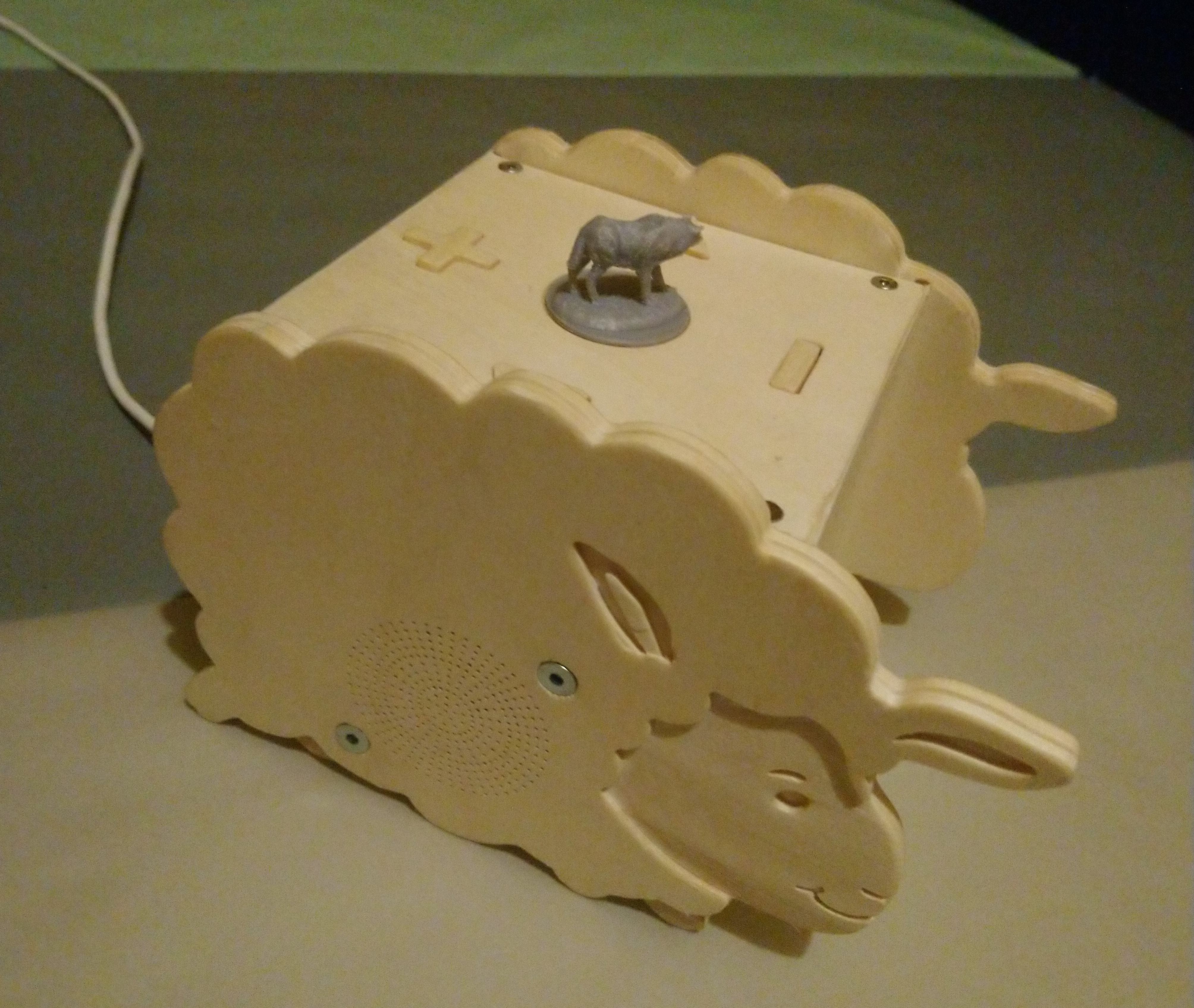
A children's juke box controlled by RFID tags, based on an ESP32.
- Playback of user-defined MP3 playlists
- Playlist selected though RFID tag. Cheap RFID stickers can be placed on any 3D printed model.
- Battery powered, can play while charging
- Four buttons: volume +/-, next/previous track
- Intuitive pause functionality by removing the RFID tag and putting it back on to resume (no limit in pause time, no impact on battery life)
- WiFi download of new MP3s and playlists
- Firmware upgrade via WiFi
- Long standby time (several month)
- Long play time (many hours, if not days)
- Toddler proof :-)
- EPS32 microcontroller
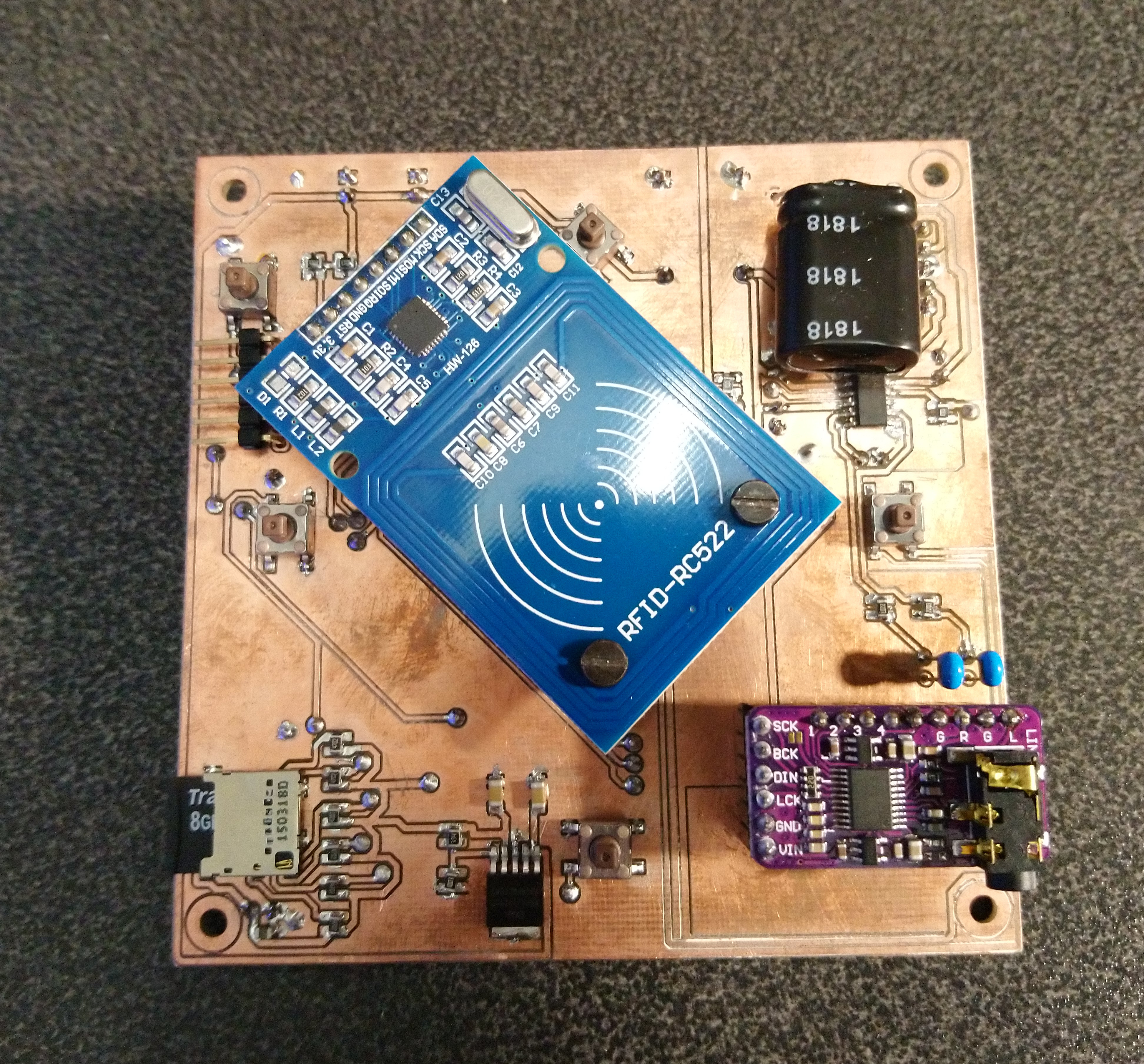
- MFRC522 RFID board
- PCM5102 I2S stereo audio DAC
- PAM8403 stereo amplifier
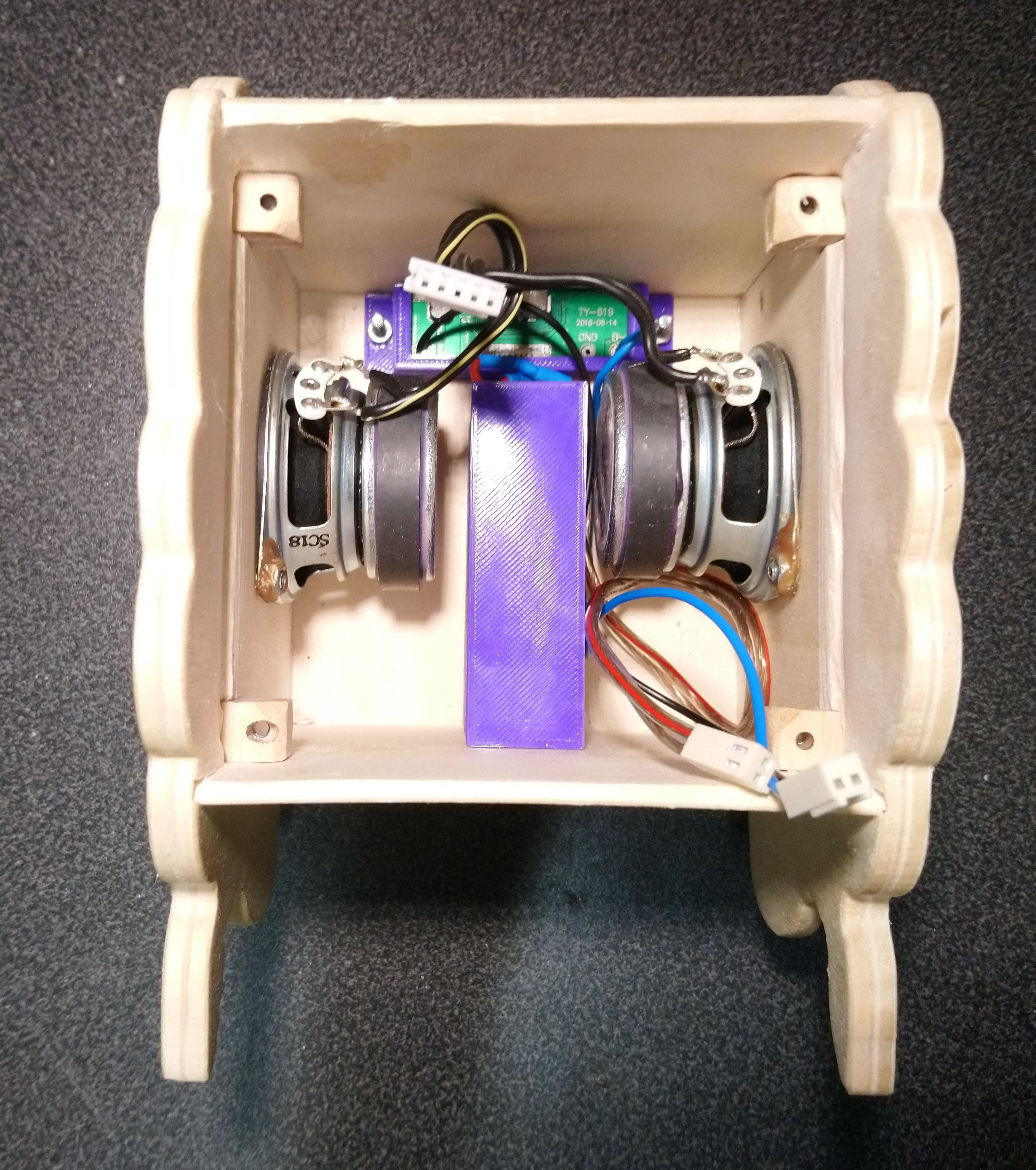
- Pair of wideband speakers
- 3.6V Li-ion battery with USB charge controller from a USB power bank (2x 18650-type cells with 2500 mAh)
- SD card to store MP3 files and playlists
At first I was considering building the box based on a Raspberry Pi. I had an old first generation Pi lying around unused, so I though it would be a good way of using it. I was immediately disappointed by its sound quality. Although this is significantly better on newer models, I learned another lession: The power consumption of a Raspberry Pi is very high, and it takes a long time to boot. Keeping it always running to wait for an RFID card to be detected is out of the question, since I wanted it to run from battery. Adding a small microcontroller (I though of some ATMega) to switch on the Pi only when a card is detected would result in long wait times until the music starts playing. Also the power consumption while playing would be still quite high. A Raspberry Pi typically uses 300 to 500 mA, while an ESP32 just takes a few mA when WiFi is disabled. After short investigation I found the ESP32-audioI2S Arduino library. This makes playback of audio using an ESP32 super easy. Thanks to the ultra low power co-processor of the ESP32 it is possible to cut down the power consumption in sleep mode to around 0.5mA-1.0mA on average (incl. periodic wakeups and RFID reads), which gives you plenty of standby time on battery.
For power supply I have used an old USB power bank which I no longer needed. It has two 18650-typed cells with each 2500 mAh and a USB charge controller with an integrated boost converted to generate 5V from the ~3.6 V battery voltage (the cells are in parallel). The 5V USB voltage is not usable to power a very low power device, since the boost converter switches off if too little current is drawn. Since the electronics anyways runs on 3.3 V, the battery voltage is used without the boost converter directly. Since the voltage can be as high as 4 V or even higher when the battery is fully chaged, and the ESP32 has a maximum voltage of 3.6 V, a voltage regulator is required. I have decided for a MaxLinear XRP6272, since it has a very low quiescent current, a quite low dropout voltage and is able to provide a high enough current so that WiFi will work without problems.
The PCM5102 has unfortunately a relatively high quiescent current, hence I decided to use two XRP6272: one for the ESP32, the MRF522 and the SD card, the second formt the PCM5102. The first regulator is permanently enabled, since the ESP32 needs permanent power, and both the SD card and the MRF522 can be powered down to a sufficiently low quiescent current. Only the second regulator is controlled by software.
The PAM8403 is directly connected to the battery voltage, since it is favourable to power it with the highest possible voltage (up to 5V). I have experimented with using the 5V USB power as a supply, but it draws too little current to switch it on. Luckily, the power down mode of the PAM8403 is also sufficiently low, so no extra switch is required here.
It is a bit difficult to measure the power consumption in standby mode precisely, because it switches between deep-sleep modes and very short bursts of RFID-activity (with only the ULP processor working in the ESP32). The average current seems to be around 1mA. Since the battery cannot be used to its full capacity, because the voltage is getting too low at some point, the lifetime is a bit below the theoretical 5000hours = 208days. Even if it were only half of that, it would be still nothing to worry about too much.
Also to get down the power consumption, I have removed the LED from the MFRC522 board. It was always on even while the MFRC522 was put to standby and hence was unnecessarily drawing a significant amount of power.
The firmware is based on Arduino and uses the following libraries:
- ESP32 I2S audio library: https://github.com/schreibfaul1/ESP32-audioI2S
- ArduinoOTA (from Arduino library manager)
- ArduinoHttpClient (from Arduino library manager)
It also uses the ulptool (https://github.com/duff2013/ulptool) to program the ULP (ultra low power co-processor) of the ESP32.
Please have a look at the header of the Arduino sketch for instructions how to build the firmware. You will also have to create the wifi-key.h header file containing your WiFi credentials and the URL to download MP3 and playlists from (see section "Server setup for playlists and MP3 files"):
// Create wifi-key.h, put the following two definitions in and replace the **** with your WIFI credentials.
String ssid =     "****";
String password = "****";
String updateCard = <cardIdToActivateWifiUpload>;
String baseUrl = "http://url.to.download.new.card.content"
The <cardIdToActivateWifiUpload> is the RFID card id (as an integer, prefix with 0x for hex format) which will trigger entering the WiFi firmware update and playlist/MP3 download mode.
The ULP periodically queries the status of the RFID card, wakes the main CPU if a new card is detected, and informs the main CPU of the current card ID and when the card is lost. Writing this code was the actual fun part of the firmware development for this project. The ULP is a very minimalistic CPU, there isn't even a (complete) C compiler (I wasn't able to get the experimental ULPCC compiler to work at all). So I had to write assembler code. There are only very few registers. The CPU doesn't even have a stack, but you can implement one (see stack.s). Since the ULP does not have access to the peripherals (they are powered down anyway), the SPI communication with the MRFC522 has to be bit-banged through normal GPIO pins. To get this right, I have basically observed the communication of a normal Arduino program using an MRFC522 library with a logic analyzer. Then I have basically coded the same sequence of bytes into the ULP program (see init_sequence section in rtcio.s). The only goal was to read the ID of the card, which is luckily not so hard to achieve. Even though some error checking is missing, the communication seems to be pretty reliably.
Since the ULP can also run when the main CPU is active, it will keep monitoring the presence of the RFID card and inform the main CPU when it is lost. The main CPU will then shutdown. An interesting fact about the ESP32 is also that the main CPU will be completely shutoff while in deep sleep mode, so when the ULP wakes it, it will boot the program from the very beginning (i.e. it will go through setup() again). Only by looking at the wakeup cause it is possible to distinguish this from a cold boot. All memory content (apart from the ULP accessible memory) will be lost, too. For this particular purpose this is perfectly fine, since the box does not need to store big amount of data while sleeping. Only the current volume setting and the last playback position is stored in the ULP memory.
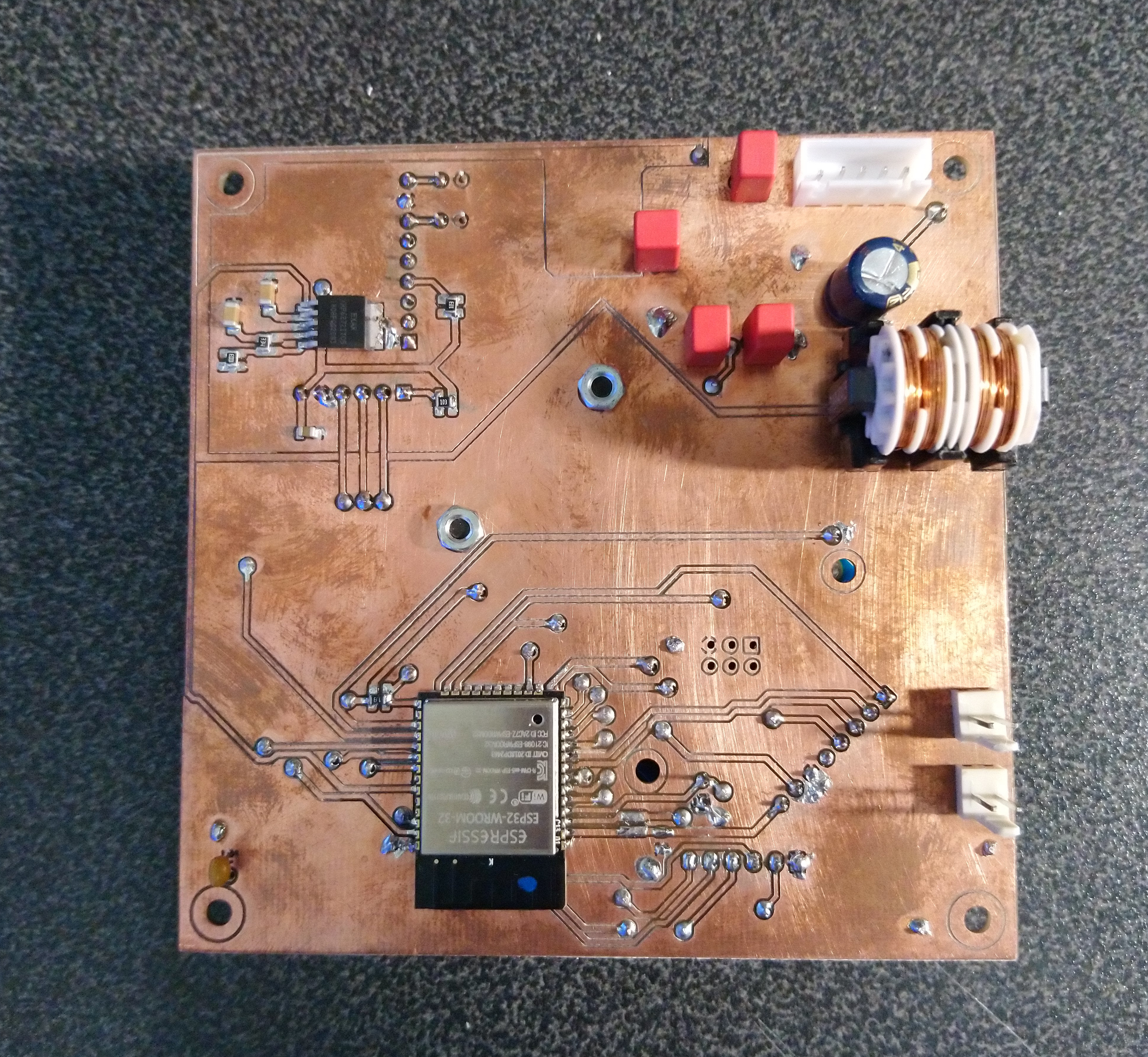
- Analogue part is well-separated from digital part, to avoid any influence of RFID or WiFi operation on sound quality.
- This works well, there is no audible noise from RFID or WiFi.
- Some things may be a bit cheated: digital signals (I2S etc.) going to the analogue side should better be decoupled with opto-couplers, because ground levels might be different. It seems to work well like it is, though.
- Some components (choke, analogue supply bypass capacitor) are quite overdimensioned, just to be on the safe side.
- I did that to avoid the risk of needing a second order with only a few parts, if I would estimate wrongly...
- Placement of some components was not smart:
- The serial programming connector was originally planned as an upright connector, so it can be reached while the board is inside the box. This collided with the RFID board, so I changed it to an angled connector. This is a bit unhandy, because it requires taking the board out when using it. Also no big deal, since there is WiFi firmware upgarade...
- Some bigger components, especially the choce, are placed a bit too close to the edge, which makes assembly a bit hard.
- Keep the area below the WiFi antenna free (no ground, no signals). This is hard to achieve with a home-produced board with just two layers, but at least one could move the signals as close as possible to the edge of the area and remove the ground plane there, ideally with a real cut out in the board.
- I am not an electronics engineer, surely one can do a number of other things better, too!

- The outer parts are made from plywood with a CNC mill.
- Don't look to close at my work. This was the first time for me do build such a case with my CNC mill, which is more like a 3D printer that can also mill...
- The buttons are also made from wood, which creates a uniform look. The reset button can be triggered with a paper clip.
- The wood is finished with wood wax.
- The holder for the battery and the charge controller are 3D printed.
- The corners holding the electronics have nuts glued in from the bottom.
- Spacers are required between the electronics and the top lid of the casing.
- Speakers are secured with screws and nuts. To simplify the assembly, I have glued the nuts to the speakers.
- The drilled holes for the sound to exit the box are too small, this degrades sound quality a bit unfortunately.
- Assembly is slightly tedious due to the spacers between electronics and the lid, but thanks to Wifi connectivity this needs not be done often.
- Also the box is a bit too small for the electronics board (or the board is to big). I had to grind some material off the walls on the inside to make it fit.
- A web server needs to be setup which provides playlists and MP3 files
- The web server needs to be reachable by the box when connected to the WiFi defined in
wifi-key.hthrough the specified URI.- It is strongly recommended to restrict access to the web server to your local network or even just the IP address of the box, to avoid exposing copyrighted material to the internet.
- When detecting the special
updateCard, the firmware will download a file called0.lst.manifest, which contains a list of file sizes and names (one entry per line). - It will then check each entry whether the file exists on the SD card and its size matches. Any missing or wrong-sized file will be downloaded. Any extra file will be deleted.
- Playlists need to be named after the card ID which should activate the play back of the list:
<cardId>.lst(e.g.deadbeef.lstifdeadbeefis a card id). They simply contain a plain list of MP3 files which should be played back in sequence. The playlist file and all MP3s need to be in the manifest file, so they are properly downloaded. - During playback, there normally is no WiFi connection to safe power. It is possible though to have web radio streams in the playlists. If a playlist entry starts with
http://, WiFi will be activated before the stream is started. Note that this will work only with MP3-based streams, and it will reduce the battery life considerably. - To generate a playlist on a Linux system, use the script
scripts/makeList.sh. - To generate or update the manifest, use the script
scripts/makeManifest.sh. - Do not use non-ASCII characters in file names. Use the script
scripts/fileRenamer.shto rename files such that those characters are avoided. - To correct the sound distortions caused by the small holes in the casing letting, I use the script
scripts/soundCorrection.sh. I would recommend rather making those holes bigger, but if you face similar issues this can be helpful. - If you have a Youtube Music account and want to download MP3 files from there to the box, have a look at the scripts
scripts/ytmSetup.pyandscripts/ytmLoader.pyand modify them for your needs.