Installation SmartHome.pi (english)
I do now that there are many different hardware setups around. In order that you don’t waste your time reading this document here the setup which is the basis for this manual:
- Some KNX actors (switch, blinds, heating)
- Some KNX sensors (4/8 sensor)
- ETS GAs programmed and working
- KNX IP interface (router) on DHCP
- Dlink router running DHCP server (not connected to the Internet) , WLAN
- Raspberry PI type B, headless mode
- Notebook, iPAD, iPhone for connect to Web services
I’ve mounted the hardware into a dedicated suitcase to play around with it without interfering with my production LAN/WAN setup @home
##Version Control
- 1.0 Release to Forum 20.Feb. 2014 (Mario)
- 1.1 Important Directories, version control 24.Feb.2014 (Mario)
- 1.5 Converted from PDF to Markdown format 08.Apr. 2014(Mario), (Current Version)
##Table of Content
Lets Start (Basic Installation)
- Basic Linux knowlegde
- Raspberry PI and a SD Card (2GB or bigger, Class 10 recommended)
- IP KNX Interface (or KNX Router)
- HDMI Monitor, USB Keyboard
- Internet connection
- Portable PuTTY (SSH)
- Portable WinSCP
- Portable Notepad++
- WinDiskImager
- The latest Smartvisu Raspberry image compilation
Basic Linux knowlegde
In order to have success we tried to keep this manual as comprehensive as possible. But it does not help you do have some basic understanding of Linux and command lines of course
Raspberry PI and a SD Card (2GB or bigger, Class 10 recommended)
Basic hardware needed. As for the SD Card a Class 10 speed is recommended as this allows the the raspberry to read/write with adequate performance.
IP KNX Interface (or KNX Router)*
There are many ways to Rome. This manual explains the connectivity using an IP KNX interface. There are other ways like busware.de using the ROT extension or you can use a KNX/USB interface to connect to the bus attaching it directly to the Raspberry.
HDMI Monitor, USB Keyboard
For the initial setup of the Raspberry it is useful to have it attached to a monitor, USB keyboard to run it directly from the console. Afterwards you can run it in headless mode.
…. Just a thought
Internet connection
Attach the Raspberry to your LAN which is connected to the Internet if possible. Internet is needed to install additional packages and to update the system and to get the current date/time for the raspberry
Portable PuTTY
I recommend to download this handy tool for getting the SSH sessions on the machine to run the raspberry in headless mode without keyboard/monitor
Portable WinSCP
I recommend using this easy to use “Explorer” to connect to the Raspberry and do file transfers from/to the raspberry. Important always write using the UTF-8 format
Portable Notepad++
I recommend using this tool to edit the html pages because of the code highlighting. You can configure WinSCP to start this as Editor. You should take care you always save file using the UTC-8 Encoding when using it on Windows

WinDiskImager
The Windows tool to write the image to the SD Card and to read from SD Card to create Backups
The latest Smartvisu Raspberry image compilation
This Document was written based on the Image 2013-11-16.img. Any later image settings and other stuff may not apply anymore.
##Lets Start (Basic Installation)
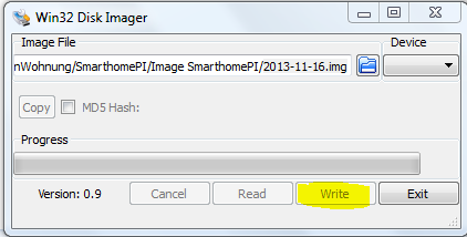
Install image using WinDiskImager
Put your SD Card into your Win Computer and start WinDiskImager. Select your downloaded Raspberry PI Smarthome/SmartVisu image and press “write”
Disk Image with MAC http://seeholzer.net/raspberry-pi-via-mac-os-x-aufsetzen/
Reboot for first time
Be sure you’re connected to the Internet with the Raspberry the first time you boot the new loaded image.
Initial UserID/Password for the system is: admin/admin
Resize image (optional)
As I am using a 16GB SD Card I decided to extend the existing partition. This is an optional step depending on your hardware
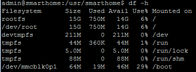
- Connect via PuTTY to the Raspberry (Login admin, pw=admin)
- If you type df –h you will see how much disk space is available.
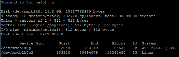
- Now starting FDISK. Command : **sudo fdisk /dev/mmcblk0 **
- Type „p“ to display the current blocks of the SD card.
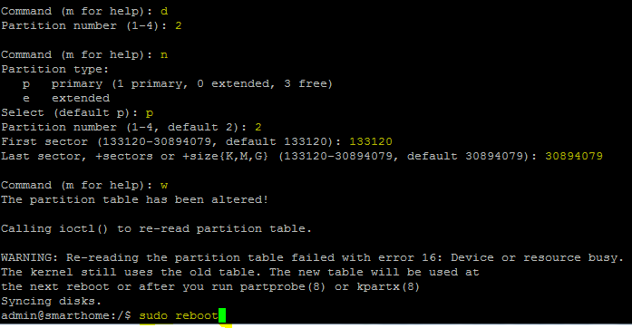
- Next parameters to type. „d“ (for delete) and “2” for choosing the 2nd partition. Don’t be afraid. Only the Partition table is deleted, not the content.
- Now it’s time to create that primary partition again using the entire SD card space. Type “n” and “p” using the value from above.
- Finally type “w” to write that values to the partition table.
- Then reboot
Configure (KNX) IP interface
Note: if you’re not using an IP interface have a look on the smartvisu help pages for
configuring other interfaces
Now use WinSCP to browse to the /etc/default/ directory and edit the file called eibd
If you’re using an KNX/IP interface than change the following parameters:
- EIB_ARGS="--daemon --Server --Tunnelling --Discovery --GroupCache --listen-tcp"
- #EIB_ADDR="0.0.0"
- EIB_IF="ipt:192.168.0.111" (use the IP address of your system of course - means e.g. KNX Gateway)
- EIB_UID="1000"
Save the file
Restart EIBD services
restart EIBD using the smartcontol.local Web Interface or via puTTY from the command line “/etc/init.d/eibd restart”.
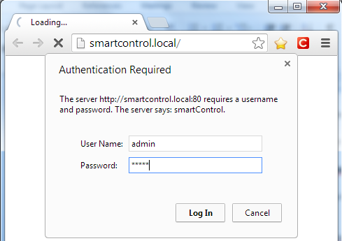
(Password is still admin/admin unless you have changed it)
Then press “show services”
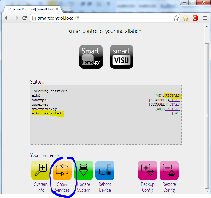
Then press: "Restart" the eibd service
Check KNX connectivity
Now you come to your first milestone. Can you address KNX group addresses via the Raspberry PI?
On the PuTTY command line you use the command “groupswrite”. A parameter value 1 is “on” , 0 is “off”. This is of course only true for Boolean type. Other GAs may work with numbers instead. Please read documentation about GA values separatelly. Pick a switch actor of your KNX installation and note down the group address you have configured using the ETS software.
- groupswrite ip:localhost 0/0/67 1 (for on)
- groupswrite ip:localhost 0/0/67 0 (for off)
ET voila, your lamp or whatever you have selected should now turn on/off.
Setup of KNX/Visu plugins
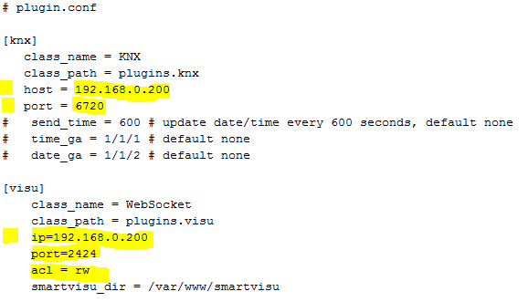
Next step is to configure the plugin.conf file from the /usr/smarthome/etc/ directory
- Remove the hash on the knx section for host and port and add the IP Address of your raspberry.
- Remove the hash on the visu section for ip, port and acl , add the IP address of your raspberry and change the acl to read/write “rw”
##Setup of Smartvisu
Basic understanding of important folders and their structure
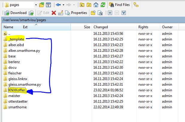
There are some important directories
- var/www/smartvisu/ The directory contains the config.php file. This file contains the configuration of your project. E.g. what pages subdirectory being used for your visualization and what color your project use.
- /var/www/smartvisu/pages/ The base directory of the html pages. You will find interesting pages of other projects you can learn/copy from too there.
- /usr/smarthome/items/ The base directory for the items you want to control in a structured way (KNX addresses, options, Floor structure, Room Structure)
- /usr/smarthome/etc/ The directory where you find the plugin.conf file. In the [knx] and [visu] section you define the connectivity to your project.
- /etc/default This directory contains the file eibd file. This file contains the interface address (in my case the IP address of my IP router
Setup of one new “Item” for test
I recommend to use the same group address GA you have successfully used for the initial groupswrite test. You will find a smartvisu.conf file on /usr/smarthome/items/ you can use to start with. Create a backup of this file and follow with the next step. Now we replace the content with a single GA placed into a “room”.
If I've understand the structure correctly we have 4 layers max. Each individual layer has its own bracket marker “[ ]”.
- Layer one [ name ] : Used for Floors or central functions
- Layer two [ [ name ] ] : Used for Rooms or structure
- Layer three [ [ [ name ] ] ] : Used for the individual Item
- Layer four [ [ [ [ type ] ] ] ] : Used for describing the action of a item. This corresponds to the KNX GA address. Like “On/off” or “dimm”
However you don’t need to use all 4 layers. For a simple project a layer one and two might be enough to display all the items you have.
Here my example
[1stFloor]
[[LivingRoom]]
	[[[Spot]]]
		[[[[OnOff]]]]
		type = bool
		visu_acl = rw
		knx_dpt = 1
		knx_listen = 1/1/1
		knx_send = 1/0/1
		knx_init = 1/1/1
- type = bool – The attribute only has two states (True/False)
- visu_acl = rw – rw = read and write / ro = read only.
- knx_dpt = 1 - The datapoint (dpt) of the Item is 1
- knx_listen = 1/1/1 – The item listens on the GA 1/1/1
- knx_send = 1/0/1 – The Items sends to the GA 1/0/1
- knx_init = 1/1/1 – The Item will be initialized upon boot from smart home
More details for KNX options you find on: http://smartvisu.de/kurzanleitung/index.php?page=grundlagen_item
 Note: It is important to understand this structure as  when setting up the html pages you refer to these object(s)
 in the way of “1stFloor.LivingRoom.Spot.OnOff”
Now save the smartvisu.conf file with your first Item object.
Restart smarthome.py
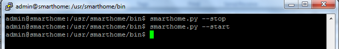
Important: Each time you change the Items or the html file you need to restart Smarthome. Command for doing this:
- /usr/smarthome/bin/smarthome.py –stop
- /usr/smarthome/bin/smarthome.py –start
Creation of Visu html Folder
From the folder /var/www/smartvisu/pages/ you find a subfolder called **_template. Copy this folder and its contents into your new project folder
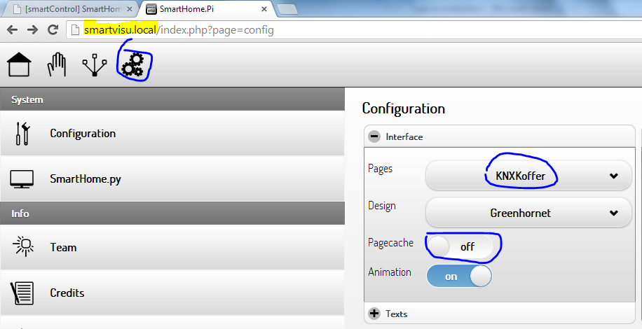
Change Smartvisu config to new project folder
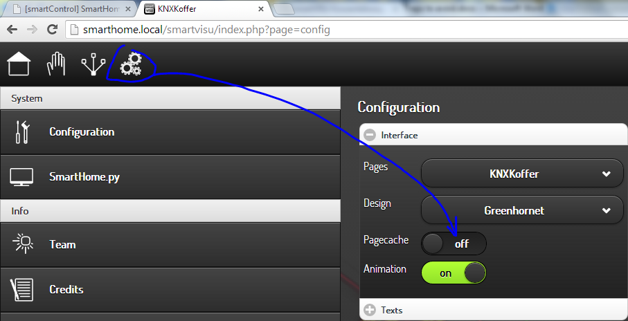
Now as you do have created your own pages folder structure you can change SmartVisu config to get to know about this. Go to http://smartvisu.local/ and select the config option (the one with the 3 gearwheels)
On the interface section select your new project folder. Take care you uncheck the caching as otherwise changes are not immediately reflected on reload. It will take longer to load but during setup of your pages this is more helpful to run it this way.
Alternatively you can edit all these settings directly on : /var/www/smartvisu/config.php
Note: Don’t forget to press the big “SAVE” button on the bottom of this page once done.
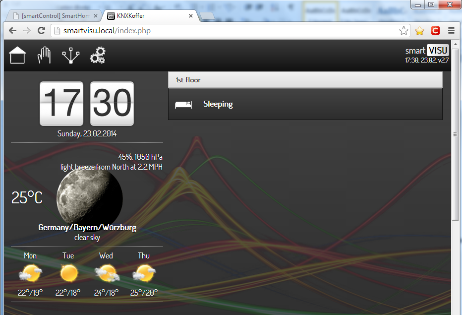
Start your Project visu the first time
You can now press the Home icon and you will see an “almost” empty page which content is based on:
- what you have copied from the “_template” folder
- in particular the settings of the config.php file from the var/www/smartvisu folder
- The content from the index.html (var/www/smartvisu/pages/) .
- The content from the rooms_menu.html (var/www/smartvisu/pages/)
So far so good :-)
Creation/Modification of your first Main Page
I will just explain some basic editing here. For more details have a look on the nice online docu for editing pages. But as it took me a little while to understand I though you should have it a bit easier than me.
In simple terms:
- Index.php loads config.php (to know which project , pages/)
- then loads a base project (from Pages directory)
- then loads Index.html from project directory
- then loads rooms_menu.html from project directory
Then loads room_sleeping.html (if clicked)
              Ideally we do have a visualized Architecture picture here.
              At presence this is far away from the details I’d love to have
              feel free to share if you have more!!
Now Edit the rooms_menu.html (var/www/smartvisu/pages/). And make some modifications like:
And save it. You will now have a Main Heading called My 1st floor and a new reference link to a “subpage” called room_living.html with a nice icon displayed called scene_livingroom.png.
E.g. If you now reload your smartvisu page it should look like this:
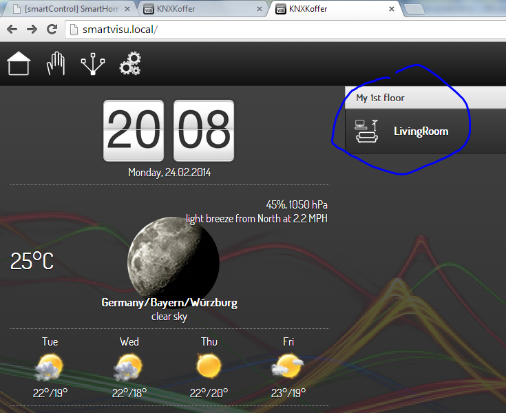
Of course there is no such livingRoom.html yet....
Creation/Modification of your first Rooms Page
Copy the rooms.html into room_living.html using winSCP. Then edit this html file
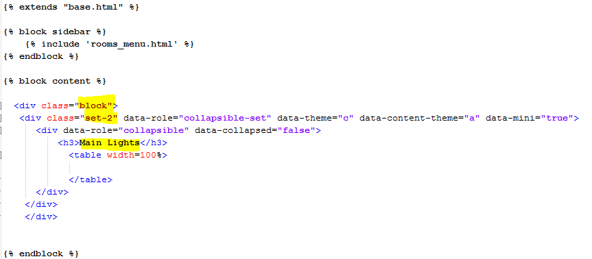
We are now creating a new so called Block “Type2” . Please refer to the smartvisu docu for more details on Blocks. There are about 5 different type you can choose from.
Insert the following code:
…and reload the page . Should look like this
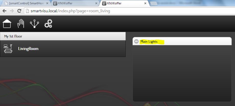
…I know… nothing fancy yet :-)
Entering your first Item
Within the same rooms_living.html we add the one Item we have created in the very first beginning. Do you still remember? Really… I didn’t :-)
OK, it was called 1stFloor.LivingRoom.Spot.OnOff. Go have a look on the smartvisu.conf from the /usr/smarthome/items/ folder if you like.
Now please add the following Code to the rooms_living.html:
 <td align=left>
 {{ basic.switch('S1', '1stFloor.LivingRoom.Spot.OnOff', icon1~'light_floor_lamp.png', icon0~'light_floor_lamp.png') }} Living Room Spot
 </td>
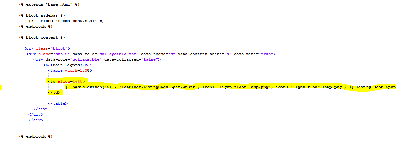
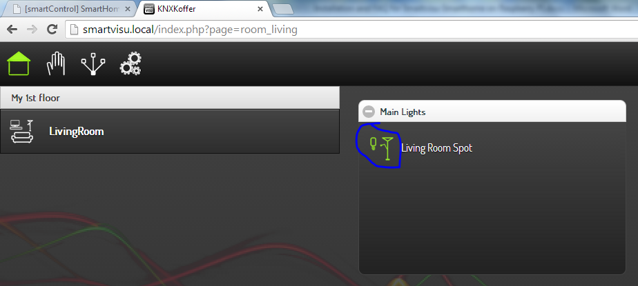
And reload your page once again. It now should look like this:

Final Milestone “press the living Room Spot”
Hooray your Living Room Spot should now be turned on/off if you press the icon
Final Cleanup
- Stop smarthome.py in Debug mode if you still running it this way
- Enable Pagecache:on from the smartvisu config section
Your next steps
- Adding more “items” (use your house structure (Floors, Rooms, Groups, Items)
- Creating all your html pages for the very same house structure
- Adding your Items to your pages , block content structure
- Learn more about all the possible the visualization options
- Have some fun :-)
Change Keyboard console to “DE”
In case you’re using a German USB Keyboard attached to your raspberry and you have attached a HDMI Monitor to your raspberry you may wonder how to change they Raspberry keyboard layout to German. Here we go: Probably a package is missing so haven’t found out yet. The command sudo dpkg-reconfigure keyboard-configuration does not work. Anyway via PuTTY I do have my german layout so not that important anymore.
- sudo apt-get update
- sudo apt-get install apt-utils
- sudo apt-get install keyboard-configuration
In case not connected to the Internet when using the Raspberry
You may wonder. But I’ve decided to run the Raspberry and my KNX components for testing on a dedicated “offline Wifi Router”. I realized that in such circumstances the network clock update is not working! All the time you boot you end up having a 1970 start date! As the Raspberry does not have an RTC onboard there is no direct way out of this. Options:
- You can buy cheap Real time clock RTC extension for the Raspberry
- You can run the command “sudo date –s “14 Feb 2014 20:20:00” after each reboot (pretty annoying to set this manually each time)
- You can install the tool fake-hwclock (saves date/time on shutdown). Not ideal but works.
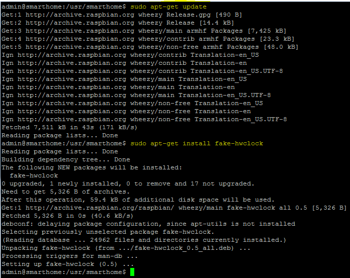
In case you want to go for the fake-hwclock:
- Command : sudo apt-get update
- Command : sudo apt-get install fake-hwclock
Entering smarthome.local does not work on your machine
I have made that interesting experience. You most likely realize this issue when you don’t call any “i” devices your own and do not have iTunes installed on your computer. Root cause was the missing so call mDNS service (Bonjour Service) on my computer. You can find information on this issue on : www.howtogeek.com/167190/how-and-why-to-assign-the-.local-domain-to-your-raspberry-pi/
In this case this is nothing tragic you still can use http://<ipaddress_of_Raspi>/smartvisu . But we should tell people I thought.
Smartvisu Pages do not refresh
In case you forgot. During you edit pages you should disable caching on the config page. This will slow down load times however on html page reload your changes are displayed immediately.
Could not connect to smarthome.py server! Websocket error
After creation of the first “pages”I always got a red triangle on the upper right corner of the web page called “error”. Message was: “Could not connect to smarthome.py server! Websocket error undefined.”
I’ve fixed this by editing the plugin.conf file from /usr/smarthome/etc directory and putting in the IP address, Port of the raspberry the corresponding [knx] and [visu] section.
plugin.conf
 [knx]
 class_name = KNX
 class_path = plugins.knx
 host = 192.168.0.200
 port = 6720
 \#   send_time = 600 # update date/time every 600 seconds, default none
 \#   time_ga = 1/1/1 # default none
 \#   date_ga = 1/1/2 # default none
 [visu]
 class_name = WebSocket
 class_path = plugins.visu
 ip=192.168.0.200
 port=2424
 acl = rw
 smartvisu_dir = /var/www/smartvisu
Reboot / Shutdown
Probably most of you will know, but there are people like me with 10y old linux knowledge and I would have loved somebody have told me that the two commands are simply called
- "sudo poweroff" shuts down
- "sudo reboot" reboots
The important Directories
Here I follow what has been already posted many times but I thought it’s useful for this manual to have it in here too. Attached the directories that you will use most and where your project files and config files are stored:
 /etc/default
 /usr/smarthome/items
 /usr/smarthome/etc
 /var/www/smartvisu
 /var/www/smartvisu/pages
Backup
I recommend from time to time you pull of the SD card from your Raspberry put it into your Computer and write a single image file for Backup using WinDiskImager. If you have done a resize of your SD Card Do a WinZip of the created image to save some disk space.

Debugging SmartVisu
It is useful to run smarthome.py in debug mode from your puTTY session to see what’s happening.
Stop the smarthome.py: smarthome.py –stop
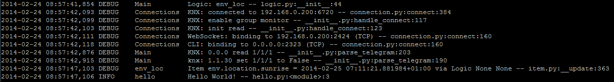
Then restart the smarthome again in debug mode with: smarthome.py -d
The console output should look something like this:
Debugging SmartHome
<Don’t know yet how to debug the web pages yet. I was told to use a JS Debugger like firebug so this will be on my to do lis\t>