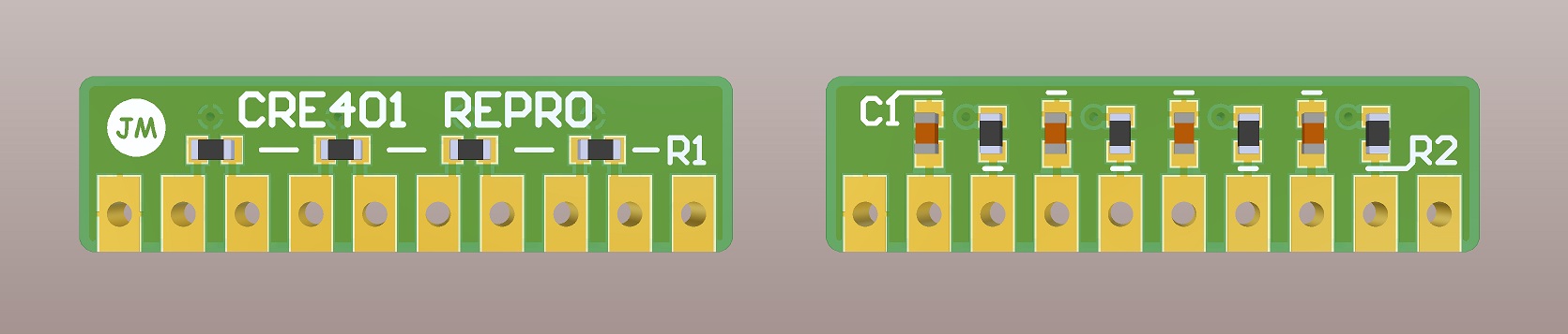
The CRE401 is a no longer produced RRC array found most commonly on SNK's Neo Geo boards. When made my MV-LED reproduction, I designed a little PCB to replace this array with 0603 resistors and caps. The boards only costs $1.40 for 3pcs at OSH Park, and I invite you to make your own!
You need the following items for one unit:
| Part | Amount | Comment |
|---|---|---|
| 330Ω 125mW 0603 resistor | 4 | Originals used 125mW resistors, but 100mW would work too |
| 1KΩ 125mW 0603 resistor | 4 | Originals used 125mW resistors, but 100mW would work too |
| 33nF 50V 0603 capacitor | 4 | I measured a range of 33-43nF in the originals |
| 10 pin 0.1" header | 1 | Vertical or right angle variants will fit |
| CRE401 Repro PCB | 1 | I got them made at OSH Park |
The following steps are taken to assemble one unit:
- Sand off pcb break-off tabs if needed.
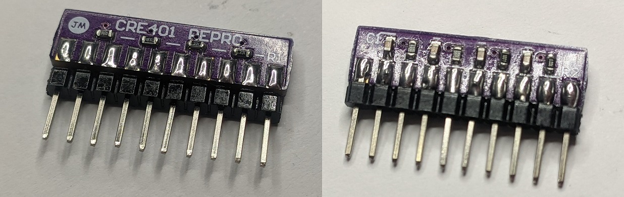
- Solder the 1KΩ resistors and 33nF caps to the back.
- Solder the 330Ω resistors to the front.
- Solder the pin headers to the front or back.
- Make sure there are no solder bridges and enjoy!
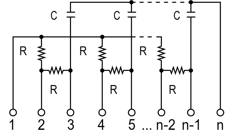
The CRE401 consist of 3 parts:
- Pull-up resistors. This ensures there is a valid 5V "high" state for logic IC's. It's needed for the MV-LED input as these use low side drivers on the MVS. It also supplies the voltage at the MVS/AES joystick and button pins.
- Series resistors. This limits the current that can flow when a wrong connection is made, like a short or a bad voltage. It also is part of the RC-filter with the capacitor.
- Filter capacitors. This forms a low pass RC filter at the output. The component values make for a cut-off frequency of about 15kHz. This means all high frequency noise above this gets filtered out to prevent strange behavior. It also protects the IC's against ESD.
The resistor values seemed to be common knowledge already, but I could not find the capacitor values. Sounds like a good excuse to get out my soldering iron and multimeter!
I removed a pair of every CRE401 type I had in my collection and measured the pins. This is the result:
| Component | CRE401-17 | CRE401-18 | CRE401-19 | CRE401-2N |
|---|---|---|---|---|
| R1 | 330Ω | 330Ω | 330Ω | 330Ω |
| R2 | 1KΩ | 1KΩ | 1KΩ | 1KΩ |
| C1 | 33nF | 35-36nF | 41-43nF | 42-43nF |
| Board | MV-LED | MV-LED | MV-2F | MV-2F |
The resistors are bang-on with every part I measured, but the tolerances for the caps are pretty big. For this design I have decided on using 33nF caps, but larger values as shown would work too.
People seem to be using just 4 330Ω resistors as a last resort when no replacement is available. This has the following consequences:
- No defined "high" input. This means you are relying purely on noise and input capacity to make the "high" input. I guess it would work out of pure luck.
- No low pass filter and ESD protection. This means you are vulnerable to pretty much all the noise to interfere, which may even help the missing pull-ups...
When you are troubleshooting your beloved MVS you can use this as a quick test. But remember: friends don't let friends substitute CRE401's with resistors.