The goal of this project is to provide a simple to use thermal controller for an infrared heating unit that can turn on/off at a specific, non-repeating date and time.
The building is infrequently used and there is no set schedule. Therefore the device need only turn the heat on at a specific time and turn it off the rest of the time. There is no repeat or low heat to keep from freezing requirement.
Your circumstances may be different. If so, fork the code and add your needs.
The physical location does not have internet access, so the unit must provide 100% of it’s own network connectivity. This is not difficult: just configure the Raspberry PI to be a stand alone wireless access point and give it a static IP address.
Security is physical. The steel sided building is basically a Faraday cage and there is no internet access inside. Therefore there is no requirement for authentication or encryption. Adding them would be a form of scope creep. I'm not saying security isn't important: the device is physically secured. Your location and circumstances may have different requirements and the Flask web application should be modified to include the correct level of security as needed, unless you want just want to ignore the lessons from Home Depot's break in through a HVAC system.
The unit is intended to be connected to the internet. The API is hidden behind a reverse proxy. An industrial hardened reverse proxy is added such that the API is not directly exposed to the internet.
To make things as simple as possible, new features
- A predictive thermal rise curve is used to calculate the time to temperature. The unit turns on the amount of time predicted before the use date time. No more guessing at when to turn the heat on to to pre-heat the building and no wasted fuel if building isn't used.
- A motion sensor is used to detect if there is any motion in the building. If there is no motion by the motion time out value, the unit turns off.
- Note: A PIR motion sensor does not work with an infrared heater. The sensor will give false motion readings as the heater is running. Switched to a microwave based motion sensor.
- Add Dynamic regression analysis for thermal rise calcs.
- TODO.
The same idea could be used for controlling air conditioning. However, the relays used are not capable of handling the load of an AC unit. An additional relay and some AC wiring would be required.
The case is 3D printed with ABS. One of the advantages of printing in ABS is the parts may be bonded with acetone. I did just this for the lower half of the case. The top cover is held on by 4) #6-32 x 3/8 screws. The middle spacer has threads molded/printed in for this.
Parts list:
- Raspberry PI model B or Zero W with Raspbian Buster
- DS18B20 temperature sensor (others may be substituted). This project used SunFounder’s PC board to eliminate the need for a breadboard or other circuit board to hold the DS18B20.
- Jbtek 4 Channel DC 5V Relay module. Make sure these are contact style.
- RCWL-0516 Motion Detector
- (20) Jumper wires
- (2) 5mm Blue LED
- 270 ohm 1/4 Watt resistor
- (4) #6-32 x 3/8 pan head screws
- (10) M2.5 x 4mm pan head screws
- Case for Raspberry PI, relay and temperature sensor boards. The STL files are posted as part of this project. Note: you may need 2 of the middle spacers.
- Android smart phone with Android 4.4 or higher
- Apple iPhone with iOS 11 or higher
The case base parts are bonded together. One of the charateristics of ABS is it desolves in acetone. A few drops bonds the lower case parts together. The cover is held on with the 4 #6 screws.
Pin out:
| Physical pin | BCM/GPIO | Connected to |
|---|---|---|
| 1 | DS18b20 temperature: VCC (3.3V) | |
| 2 | Relay board VCC (5V) | |
| 4 | Motion sensor 5V+ supply input | |
| 6 | Relay board GND | |
| 7 | GPIO4 | DS18b20 temperature: SIG |
| 9 | DS18b20 temperature: GND | |
| 11 | GPIO17 | Relay board: IN1 |
| 12 | GPIO18 | Status LED |
| 13 | GPIO27 | Relay board: IN2 |
| 14 | Status LED GND | |
| 15 | GPIO22 | Relay board: IN3 |
| 16 | GPIO23 | Motion sensor signal |
| 19 | GPIO10 | Relay board: IN4 |
| 20 | Motion sensor GND |
Pinout of Raspberry PI: https://www.raspberrypi.org/documentation/usage/gpio/
PIR motion sensor fact and how-to sheet: http://henrysbench.capnfatz.com/henrys-bench/arduino-sensors-and-input/arduino-hc-sr501-motion-sensor-tutorial/
Turn the sensitivity pot (on left) to max (clockwise) to detect motion ~7m away.
Turn the time delay pot (on right) to min (counter clockwise) so the motion detector's time delay is ~3 seconds. Never set any time parameter to less than 6 seconds because it will only cause confusion due to false positives and negatives. The reason is the motion sensor will not change state while it is in a time delay.
The as delivered motion sensors did not have a jumper for trigger selection. It only had solder pads. The high setting was used by soldering a jumper in place.
R^4 thermal rise curve:

Basic article on controlling the relays: https://elementztechblog.wordpress.com/2014/09/09/controlling-relay-boards-using-raspberrypi/
Quick & dirty how to get the temperature value: https://learn.adafruit.com/adafruits-raspberry-pi-lesson-11-ds18b20-temperature-sensing/ds18b20
##Security setups: ###Fail2ban: https://pimylifeup.com/raspberry-pi-fail2ban/
###Port forwarding: https://pimylifeup.com/raspberry-pi-port-forwarding/
The lower case 3D print in process:

Note the circuit board bosses have printed/molded threads and are filleted for stress relief.
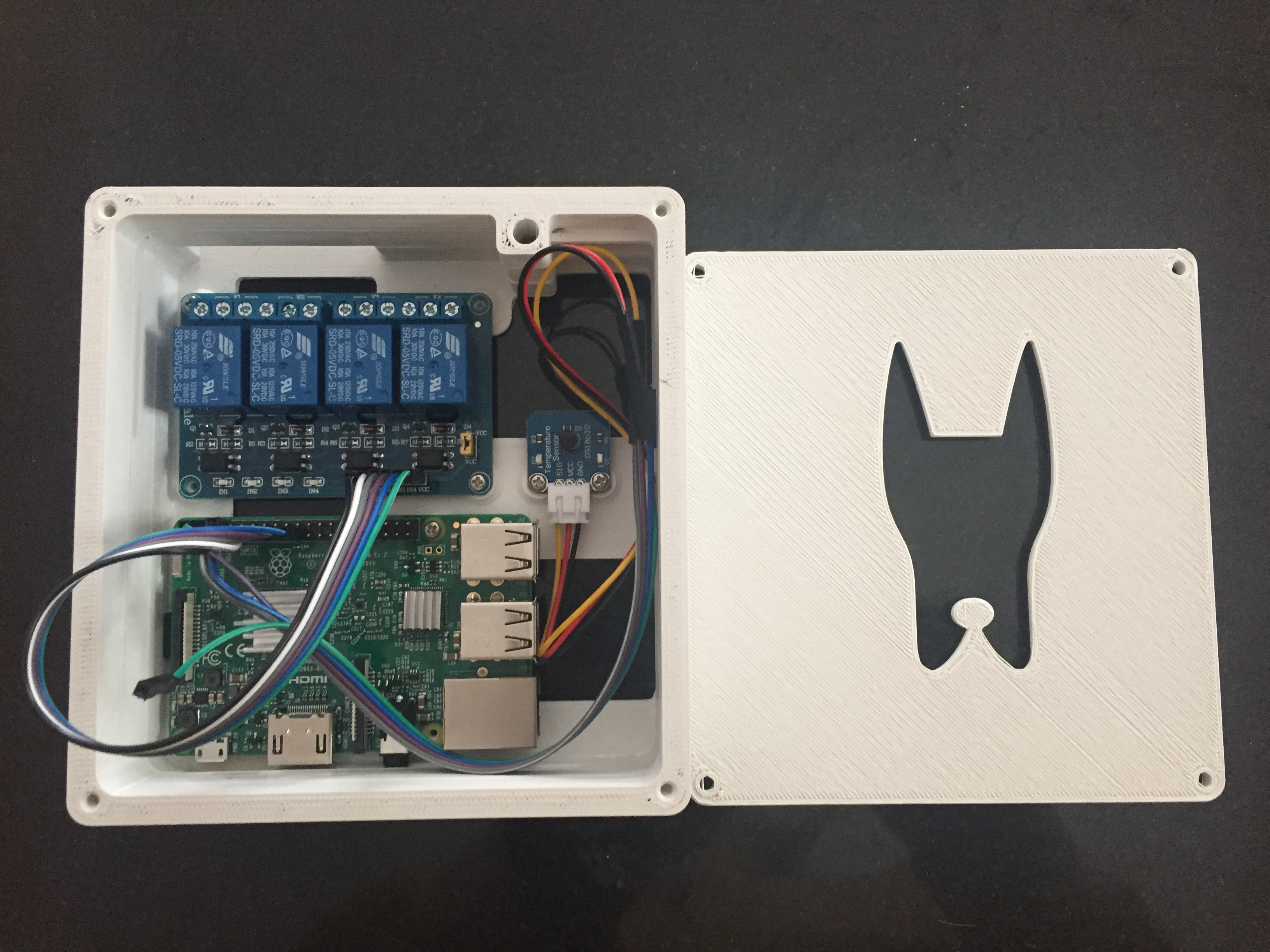
The assembled unit:
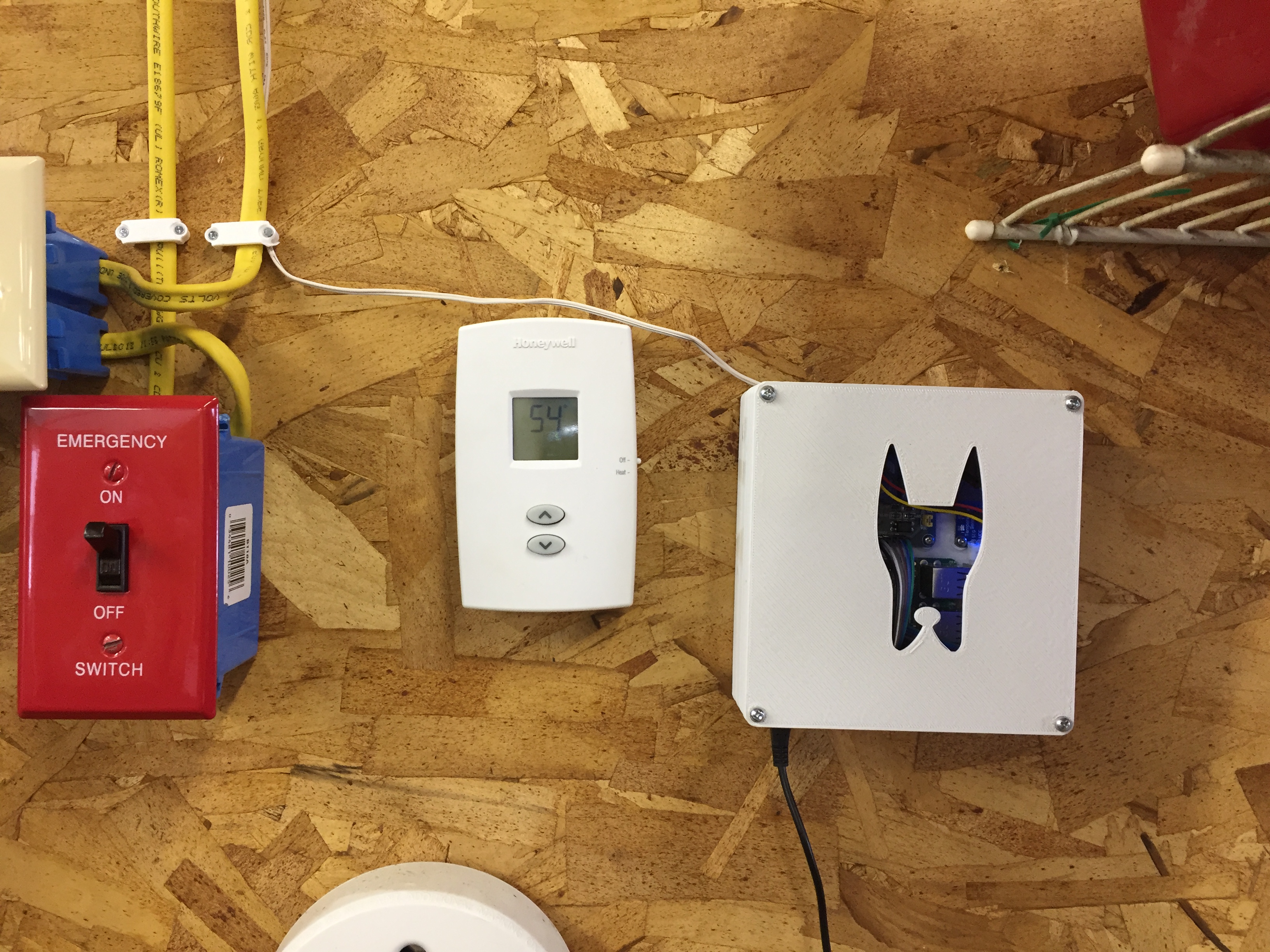
Installed and working:
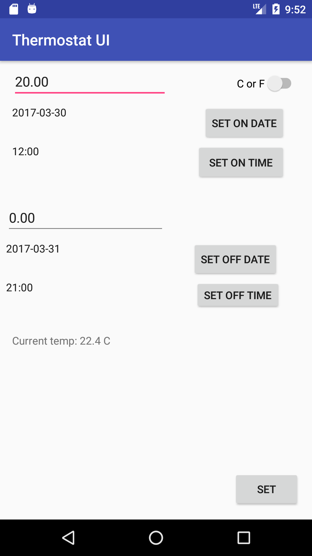
A screen shot of the User Interface (UI)
- 2021-11-28: Merging API into main
- 2022-01-07: Merging Senor UI into main