The Smart Card Removinator is a hardware device designed for automation of smart card testing with physical tokens. Testing with physical tokens often requires smart cards to by removed and inserted from the card reader to trigger things like screen locking, or simply to test multiple models of tokens or with different certificates. This type of testing is usually handled manually when testing with emulated tokens is not desirable.
The Smart Card Removinator is essentially a smart card switch that is controlled via a RS-232 serial interface. It allows for 8 smart cards to be switched to a single output that is connected to a card reader. This allows token insertion and removal events to be automated for multiple tokens.
The hardware for the Smart Card Removinator is composed of two components: a controller and a reader adapter.
The controller is based on an Arduino (Atmel ATmega32U4) microcontroller. The microcontroller provides the USB interface that is used to interface with the computer that drives the controller. The microcontroller also handles communication with the various ICs that are used in the controller.
The heart of the controller is the switching circuit that is used to actually switch between the pyhsical smart cards. Switching is handled by a set of analog multiplexer ICs are used to switch the contacts of the 8 controller card slots to a single output that connects to the card reader contacts via a card adapter. One 8:1 multiplexer is used for each contact of the smart card, allowing for 8 total cards that can be switched. The logic control pins of the multiplexer ICs are tied together so they are controlled consistently from the same signals. The controller uses Maxim MAX4638 multiplexer ICs, whose switching behavior is controlled by the microcontroller via 4 digital logic pins.
The card slots/connectors used on the controller feature a switch that is used to detect if a card is present or not. The firmware uses these for error checking (selecting a card slot that is not populated) and for status reporting. The controller uses a parallel-in, serial-out (PISO) shift register that the microcontroller interfaces with via Serial Peripheral Interface (SPI). This allows us to simultaneously read the state of all 8 card slots while using a minimum number of control pins.
The controller features a 7-segment display that is used to indicate the currently selected card slot. The display is controlled via a serial-in, parallel-out (SIPO) shift register that the microcontroller interfaces with via Serial Peripheral Interface (SPI). This allows us to simultaneously turn on the required display segments while using a minimum number of control pins.
Electrical schematics for the controller are available in the schematics directory. They are provided in SVG format. The controller is spread across 3 schematics to keep the images at a reasonable size for printing. Labels are used to show where connections are made between components on different schematics (or even within a single schematic to simplify things visually).
All of the schematics are also displayed below for convenience. You can click on the images to display a larger version.
The following schematic contains the microcontroller connector, the display circuit, and the card socket presence circuit.
The following schematic contains the multiplexer circuit and the smart card reader adapter socket.
The following schematic contains the smart card sockets as well as the A-to-B board connectors (described in more detail in the PCBs section below). This schematic is really only useful for understanding the pinout of these connectors.
The controller is made up of 2 PCBs, which stack on top of each other. They are connected via 2 24-pin header connectors. The bottom board is referred to as the A board, and the top board as the B board. It is designed this way to keep the PCB footprint from getting too large, as the physical size of the smart card slots would cause a single board design to be fairly long depending on the layout. Each board has 4 smart card slots arranged across the front edge of the board.
Board A contains the following components/circuits:
- Microcontroller (USB port)
- Reader adapter RJ45 port
- Multiplexer circuits
- Card presence circuits
- Card slots 5-8
Board B contains the following components/circuits:
- Display circuits and display
- Card slots 1-4
The pcbs directory contains Gerber RS-274-X formatted files for both of the controller PCBs. The file extensions describe which layer a file is for. The extensions map to the layers as follows:
- .top - top copper
- .bot - bottom copper
- .smt - top solder mask
- .smb - bottom solder mask
- .slk - top silk screen
- .oln - pcb outline
- .dri - drill file
The Gerber files should allow you to have the PCBs manufactured by most any PCB fabrication house. If you want to view the Gerber files, gerbv is a good open source option. Another option if you want to make design changes is KiCad, which is a full electronic design automation (EDA) software suite that includes a Gerber viewer.
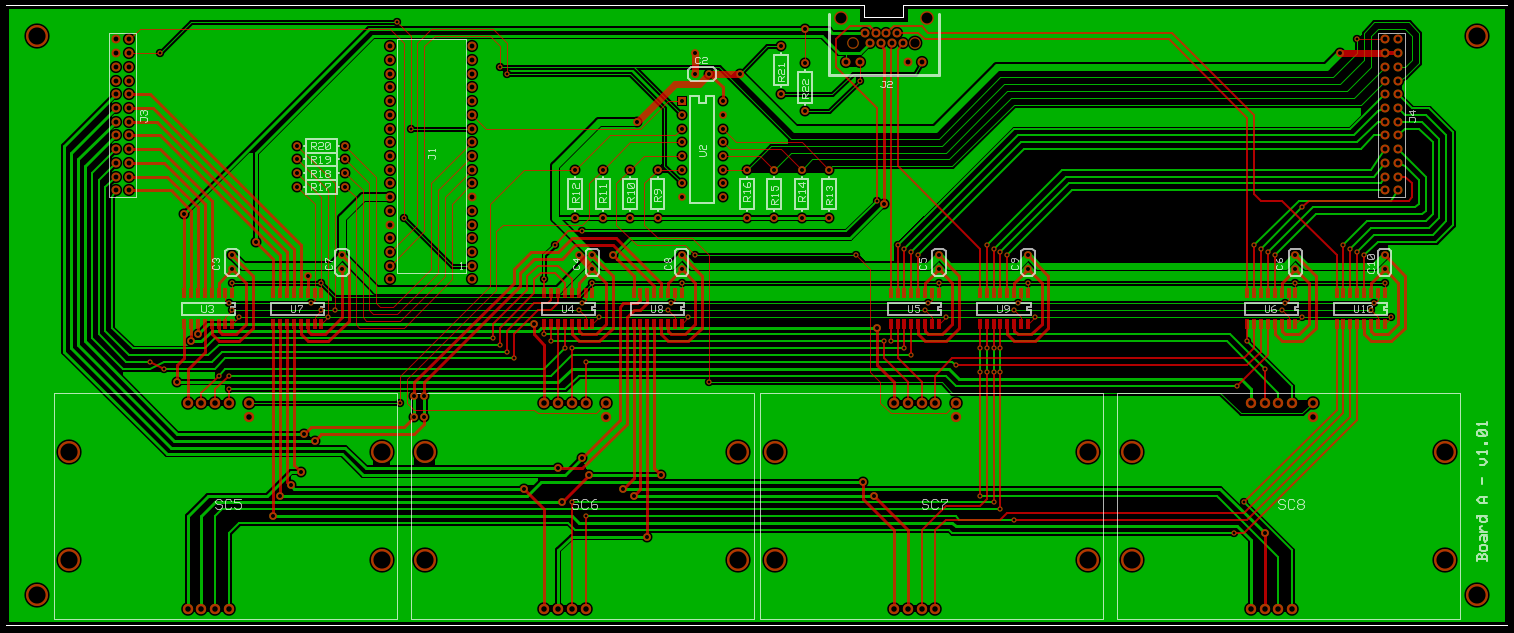
Here is an image of the board A design that was generated from the Gerber files using gerbv. The top copper layer is red, the bottom copper layer is green, the drill layer is black, and the silkscreen and outline layers are white (click for a larger version):
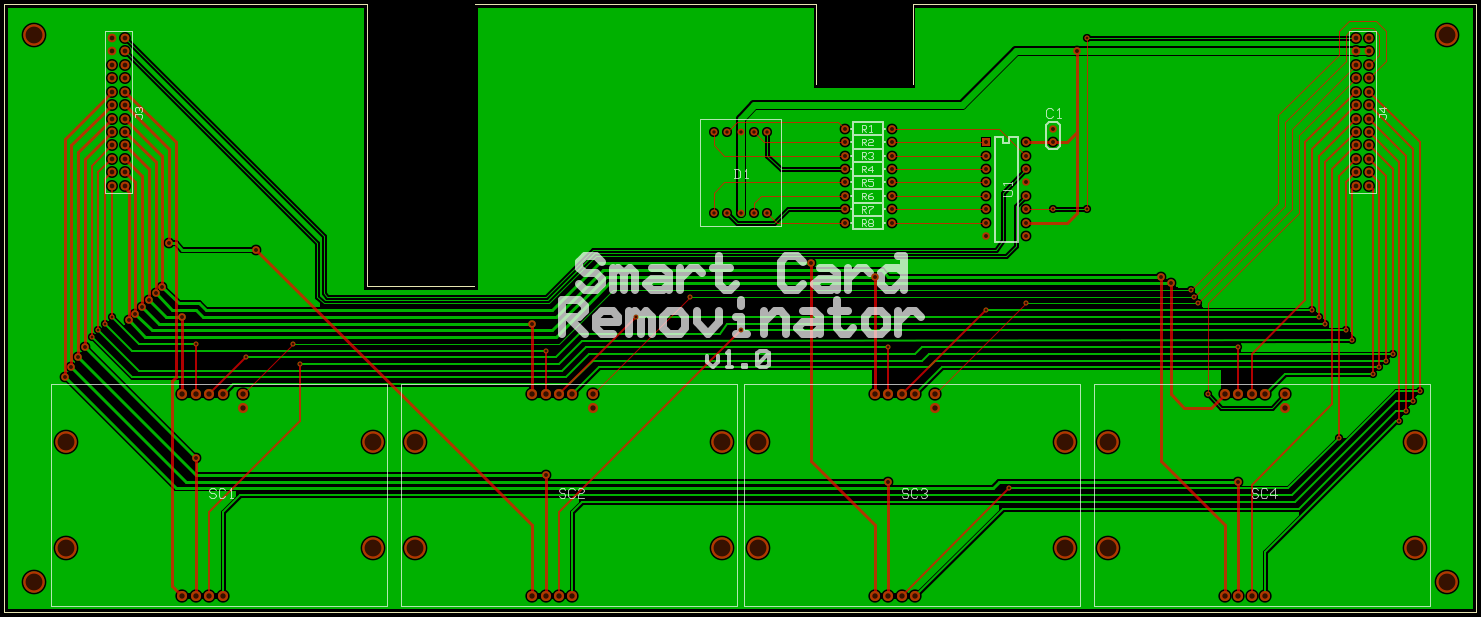
Here is a similar image of board B (click for a larger version):
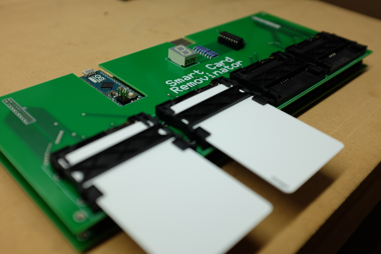
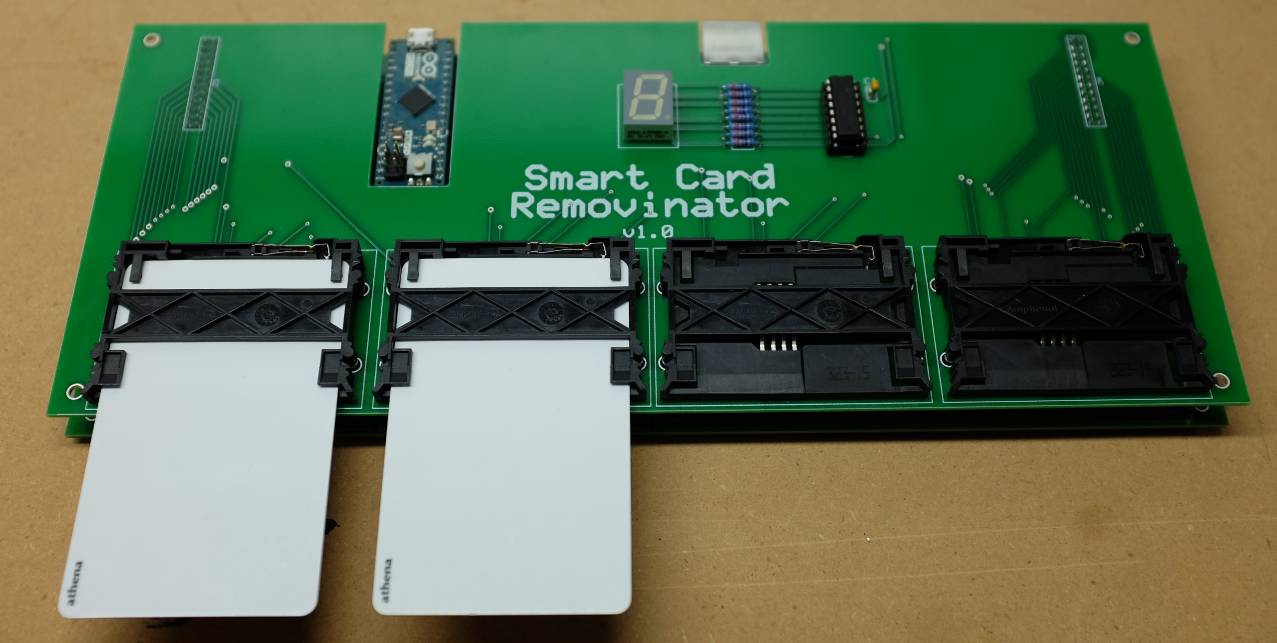
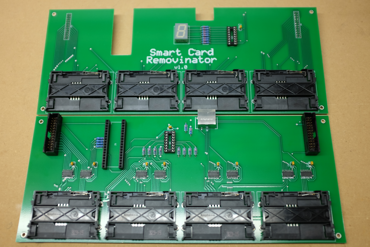
Here are some pictures of an assembled controller along with a picture of the separated boards (click for larger versions):
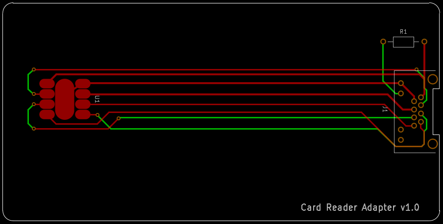
The card reader adapter is a simple PCB that has contact pads in the standard locations described in ISO 7816, which are connected to a RJ45 jack via traces. It is important that the reader adapter uses a .031" thick PCB, otherwise it may not fit into the slot of your smart card reader. The card reader adapter stays inserted in the card reader, and is connected to the controller via a standard ethernet cable.
Most card readers also use an internal switch to detect if a card is physically inserted. This is used to trigger insertion and removal events in the smart card reader drivers that operating systems use. Since the controller electronically switches cards, insertion and removal events will not be triggered. The controller can use a logic pin to control the switch in the card reader, despite the fact that the card reader adapter stays inserted. This requires minor modifications to the card reader, which are described in the Card Reader Modifications section below.
Here is a schematic of the card reader adapter, which can also be found in the schematics directory (click for a larger version):
Gerber RS-274-X files exist for the card reader adapter in the pcbs directory. The file extensions map to the PCB layers using the same naming scheme as used for the controller PCBs.
Here is an image of the card reader adapter PCB design:
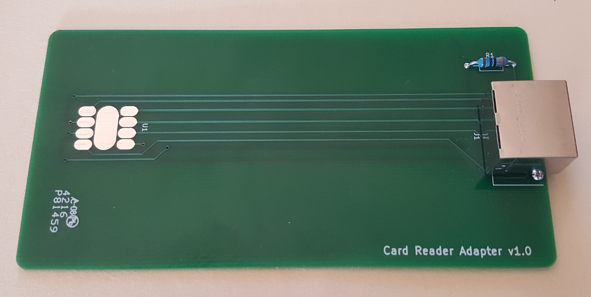
Here is an image of a completed card reader adapter:
The list of required components for the controller and reader adapter are listed below. Substitutions can be easily made for the common components such as resistors, capacitors, IC sockets, and A-to-B board connectors. Substitutions for other components may require firmware or PCB design changes, so it is recommended that you consult the component datasheets to see if changes will be required.
- (1) Arduino Micro
- (8) Maxim Integrated MAX4638ESE+
- Analog Multiplexers (SOIC-16)
- (1) Texas Instruments SN74HC595N
- Display shift register (DIP-16)
- (1) Texas Instruments SN74HC165N
- Smart card presense shift register (DIP-16)
- (1) Kingbright SA56-51PBWA/A
- 7-segment display
- (8) Amphenol C702 10M008 230 40
- Smart card slots
- (2) Amphenol RJE7318800310
- RJ45 sockets for controller and reader adapter
- (10) Vishay K104K15X7RF5TL2
- 0.1uF decoupling capacitors for ICs
- (11) KOA Speer MF1/4DCT52R3300F
- 330ohm resistors to protect LEDs (display, RJ45 LEDs)
- (8) KOA Speer MF1/4DCT52R1002F
- 10Kohms pull-up resistors for card presence circuits
- (4) KOA Speer MF1/4DCT52R1001F
- 1Kohms resistors for digital output pin protection
- (2) 3M 4816-3000-CP
- DIP-16 sockets for shift registers
- (2) TE Connectivity 6-102619-0
- Lower (A) board connectors
- (2) TE Connectivity 6-534206-2
- Upper (B) board connectors
- (2) TE Connectivity 6-535541-6
- Microcontroller header sockets
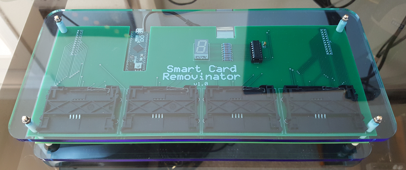
A SVG file to create a very simple enclosure is included in the enclosure directory. The design is for two identical transparent acrylic plates, which are used as a base and a top. Transparent acrylic will allow the display to be visible through the top plate. The SVG file includes a labeled 1" square as a scaling reference, which is required by some laser cutting shops when using SVG files.
Here is an image of a completed controller in it's enclosure, which was made from 6mm thick acrylic (click for a larger version):
In addition to the acrylic plates, the following components (or similar equivalents) can be used to complete the enclosure:
- (12) Bivar 911-450
- Nylon spacers for PCB mounting (.450" length, .250" OD, .125" ID)
- (4) McMaster-Carr 92005A140
- Mounting screws (M3 x 60mm x 0.5mm pitch)
- (4) McMaster-Carr 94000A330
- Acorn nuts (M3 x 0.5mm pitch)
- (4) McMaster-Carr 9540K841
- Rubber feet (.500" OD, .250" tall, .125" ID)
Note that the above screws will need to be trimmed to be about 5mm shorter to allow the assembly to tighten together properly.
The internal switch in many card readers that is used to detect if a card is physically present is usually a normally closed (NC) switch. This means that the switch is typically connected to ground when no card is present, and the connection is broken when a card is inserted. This allows us to use a common 2N3904 bipolar NPN transistor across both sides of the switch, which can simulate closing the switch even when the card reader adapter is inserted. The firmware uses digital I/O pin 8 on the microcontroller to control the state of the transistor.
Here is a schematic of the required card reader modification, which can also be found in the schematics directory (click for a larger version):
The current revision of the controller PCB does not provide a socket that can be used to connect to the card reader. A short cable with an in-line socket can be soldered to the top of microcontroller or to the bottom of controller board A for the proper pin. A future version of the PCB will add an on-board socket.
Similarly, the card reader will need to be modified to have a cable that connects to the cable added to the controller. Inside of the reader, the transistor and resistor to limit the current to the transistor base will need to be soldered and arranged to fit inside of the housing. The cable conductor should be connected to the resistor.
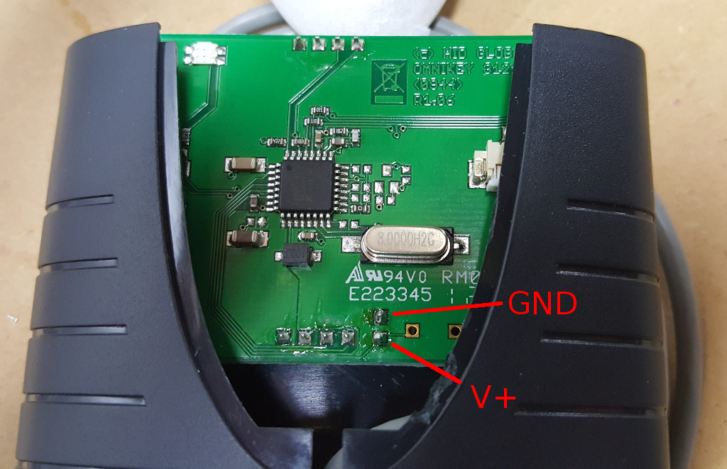
Below are some images of a HID OMNIKEY 3121 smart card reader that has been modified as described above. This first image shows where the switch contacts are located on an unmodified reader:
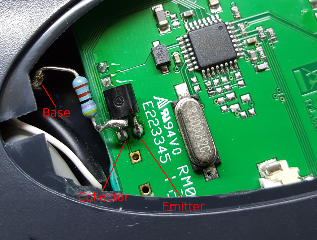
This image shows the addition of a transistor and resistor as shown in the previous schematic. With some bending and trimming of the transistor leads, the modification can be made to easily fit. The white wire is from the cable connected to the controller, which is soldered to the resistor lead on the left side of the image, which in turn is connected to the base lead of the transistor. This wire leads to the digital I/O pin on the microcontroller.
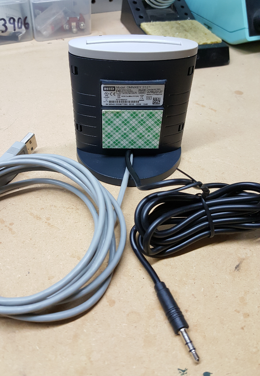
Here is an image of the reassembled smart card reader, which now has an additional cable that connects to the appropriate pins on the microcontroller:
The firmware for the microcontroller implements a RS-232 command protocol that can be used over the USB interface to control the controller. A command must be sent in an envelope, which means that it must be prefixed with a '#' character and terminated with a carriage return ('\r'). The current list of supported commands (as provided by the usage command output) is as follows:
--- Smart Card Removinator (v0.1) ---
Command Format:
	Prefix:		#
	Terminator:	\r
Commands:
	SC1	Insert card 1
	SC2	Insert card 2
	SC3	Insert card 3
	SC4	Insert card 4
	SC5	Insert card 5
	SC6	Insert card 6
	SC7	Insert card 7
	SC8	Insert card 8
	REM	Remove inserted card
	STA	Return card socket status
	DBG	Toggle debugging output
	?	Show usage information
The command responses are terse to limit the amount of data sent over the serial port, but they provide enough detail to indicate success or uniquely identify common errors.
If an illegal command is entered (missing envelope, unknown command, etc.), the following response codes can be returned:
- ERR_UNKNOWN_CMD
- A proper envelope was used, but the command is unknown.
- ERR_CMDLEN
- The command envelope prefix was used, but we didn't receive a terminator.
- ERR_PROTOCOL
- Input was received with no envelope prefix.
The SC* commands can reutrn the following responses:
- OK
- The card was successfully inserted/switched.
- ERR_NOCARD
- No card is present in the specified slot.
The REM command will always return a response of 'OK'. Using this command
when no card is currently selected is a no-op and is not considered an error.
The STA command response returns a JSON object that represents the status of
the controller and its card slots. It is composed of two attributes. The
current attribute contains the slot number of the currently selected card.
The present attribute contains an array containing the ascending card socket
numbers that have a card present. Here is an example where card 4 is currently
selected, and card sockets 1-6 have cards present:
{"current":4,"present":[1,2,3,4,5,6]}
If no card is currently selected, the "current" card will be reported as 0.
The DBG command toggles debugging output on or off. It can return the
following responses:
- DBG_ON
- Debug output is now enabled.
- DBG_OFF
- Debug output is now disabled.
Note that if debug output is enabled, debugging messages will be returned as a
part of the responses for the above commands in addition to the normal
responses. Debug output responses will always be prefied by [DBG], as can be
seen in the following example response to the SC1 command:
[DBG] Received command "SC1"
[DBG] Received status: 0
ERR_NOCARD
The ? command responds with the usage information that is shown above. It is
intended for interactive use of the controller via a terminal.
The client directory contains the removinator Python module. This module allows for Python programs to easily control the Smart Card Removinator hardware. This module is available on PyPi at https://pypi.python.org/pypi/removinator, so it can be easily installed by running the following command:
pip install removinator
API documentation for the removinator Python module is available at http://smart-card-removinator.readthedocs.io/


