GEOVIS is an all-purpose flight-path interpretation system for the University of Louisville's rocket team, River City Rocketry.
Copiers and contributers welcome!
This project draws much inspiration and several resources from River City Rocketry's Variable Drag System and Shane Tully's Osprey project.
- Geographic coordinates
- Latitude
- Longitude
- Altitude
- Speed
- Heading, relative to TRUE North
- Date & Time
- Age of last recieved Date-Time
- Other related metrics
- GPS geometric dilution of precision (DOP)
- Satellites tracking
- Age of last GPS fix
- Total NMEA sentences
- CHECKSUM EVALUATION
- Gravitational accelleration vector
- Leonhard Euler angles vector
- Heading
- Roll
- Pitch
- Linear accelleration vector
- Ambient pressure
- Altitude
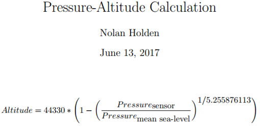
- Pressure Altitude
- Indicated Altitude (non-standard pressure corrected pressure-altitude)
- Density Altitude
- Altitude
- Temperature at sensor
- (Altitude correction for non-standard temperature and non-standard lapse rate)
- Relative humidity
- (Density-Altitude calculation)
- Example wiring between module and Teensy 3.6:
- GPS module RX -> Teensy 3.6 TX2 (pin 10)
- GPS module TX -> Teensy 3.6 RX2 (pin 9)
- Corresponding code:
constexpr uint8_t GPS_RX_PIN = 9; // Note: GPS module's TX connects to this pin.
constexpr uint8_t GPS_TX_PIN = 10; // Note: GPS module's RX connects to this pin.

Serial2.setRX(GPS_RX_PIN); // default for Serial1; unnecessary, but explicit
Serial2.setTX(GPS_TX_PIN); // default for Serial1; unnecessary, but explicit
Serial2.begin(9600);
// Note: All testing with Teensy 3.6 suggests that baud rates other
// than 9600 are incompatible. However, 9600 is ok for 5 Hz GPS
// refresh (which itself is very sufficient.)

// Encode NMEA sentences using:
while (Serial2.available())
  gps_.encode(Serial2.read());
- Default baud rate: 9600 Bd
- Default GPS sampling rate: 1 Hz
- Example I2C wiring between this IMU and Teensy 3.6:
- BNO055 SDA -> Teensy 3.6 SDA0 (pin 18 / Analog 4)
- BNO055 SCL -> Teensy 3.6 SCL0 (pin 19 / Analog 5)
- Example I2C wiring between BME280 and Teensy 3.6:
- BME280 SDI -> Teensy 3.6 SDA0 (pin 18 / Analog 4)
- BME280 SCK -> Teensy 3.6 SCL0 (pin 19 / Analog 5)
- Example Software SPI wiring between BME280 and Teensy 3.6:
- BME280 SDI -> Teensy 3.6 MOSI1 (pin 0)
- BME280 SDO -> Teensy 3.6 MISO1 (pin 1)
- BME280 SCK -> Teensy 3.6 SCK0 (pin 13)
- BME280 CS -> Teensy 3.6 CS1 (pin 31)
- Corresponding code:
constexpr uint8_t BME_MOSI = 0;
constexpr uint8_t BME_MISO = 1;
constexpr uint8_t BME_SCK = 13;
constexpr uint8_t BME_CS = 31;

// construct
Adafruit_BME280 bme_{ BME_CS, BME_MOSI, BME_MISO, BME_SCK }; // software SPI
- Connect BMP180 SCL to Analog 5
- Connect BMP180 SDA to Analog 4