Some modifications that I've made to the AR3 hardware. They are designed to be added on with minimal disassembly.
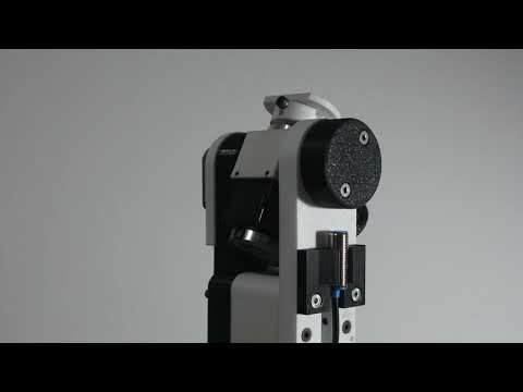
I repositioned the J5 limit switch to calibrate directly against the J6 bearing cap, which should be more accurate than using the belt carrier. I also took the opportunity to try out an inductive sensor, which I thought would be easier to position for the calibration angle than the mechanical switches. Having inductive limit switches will also help avoid cases of damaged or bent limit switches. It seems to have worked well so I'll eventually redesign and replace the other limit switches as well.
-
I use an NJK-5002C sensor along with the provided 10x2mm magnet though any other of similar dimensions that runs on 5V should work fine as a drop-in replacement, take note if you're getting an NO or NC one, you will have to make changes in the firmware accordingly
-
Magnet mount will be secured to the J6 bearing cap with two M4x10 flathead screw, replacing the existing set screws
-
Magnet can be press fit into the magnet mount
NOTE: be sure to mount it in the orientation with the correct polarity, test with the sensor first -
Sensor mount can be secured to the J6 main bearing arm with two M4x20 flathead screws, replacing the existing ones
-
The sensor mount is designed to have just enough tolerance for the sensor to slide up and down with some force applied, this is to allow you to adjust the distance of the sensor from the magnet to calibrate the sensitivity. You'll want to adjust it such that the sensor is triggered only when the magnet is directly above
-
The bearing cap is not fixed directly to the J6 housing so you'll have to manually rotate it so that the top and bottom screws are vertically aligned (see the first image below). This may require some trial-and-error - a good way I've found is to calibrate against the limit switch, send J5 to the 0-degree position through software, and then check if the J6 housing is aligned against the J5 cover spacer. After a good alignment is achieved, however, the bearing cap rotates with the J6 housing and can provide an accurate measurement of the rotation


The original rotor encoder design provides good resolution and, despite backlash and other sources of inaccuracy, works well for applications that only require repeatability. Task positions can be taught and the actual joint positions do not matter too much. However, goals produced by motion planning require accurate correspondence between the actual and intended positions of the arm. At the cost of some resolution, we can achieve much more accurate control of the arm with joint position encoders. With the AMT-102V encoders at the maximum 2048 pulses per revolution, we can get 8192 counts with quadrature decoding, giving us a respectable resolution of 0.05 degrees per encoder count which is acceptable given that there are probably other more significant sources of error.
-
The spindle adapter can be screwed over the existing J2 drive spindle, replacing every other screw. You'll need longer M3 flathead screws
-
Glue the two parts of the assembly together
-
The entire piece will snap on the the J2 turret housing


-
You can just glue the extension on to the J6 housing
-
You'll want to use the longer M3 screws for the covers to secure the adapter
-
I chose to leave the wires outside but with a little more effort you could squeeze them into the cover spacer and make everything a little neater

