Settings Guide
-
Start the Google Chrome configurator. (download it here)
-
Connect your transmitter to the computer as shown in the "Connecting to a computer guide".
-
The configurator should auto-connect to the transmitter and open the settings page.
Note that RX settings are done wirelessly. Your receiver does not need to be connected to the computer to adjust settings. No PWM or PPM will be output by the RX while in configuration mode.
-
Connect to the transmitter as above and ensure you are in the transmitter settings tab.
-
Click on the RX settings tab. Apply power to the RX during the timeout period. This can be done by applying power as normal to the airplane or helicopter.
-
The configurator should auto-connect to the receiver and open the settings page.
If you have servos plugged into your receiver and wonder why they aren't moving while you're setting things up with the configurator, this is normal: during configuration, RX signals are visible in the channel viewer on the transmitter, but the receiver doesn't pass them through to its output channels.
To test, you'll have to unplug USB from your transmitter, reboot it, and also reboot the receiver.
Well, actually it still won't work because after most setting changes on the transmitter, you'll have to rebind the receiver (hold TX button, power transmitter on, release button, hear fast beep, power receiver on, fast beep stops, power both sides off and back on, and you're in business).
See the Basic-functions-guide page for details on how binding works.
These settings are set on the transmitter and sent to the receiver during bind. You must rebind the receiver after changing any of these settings.
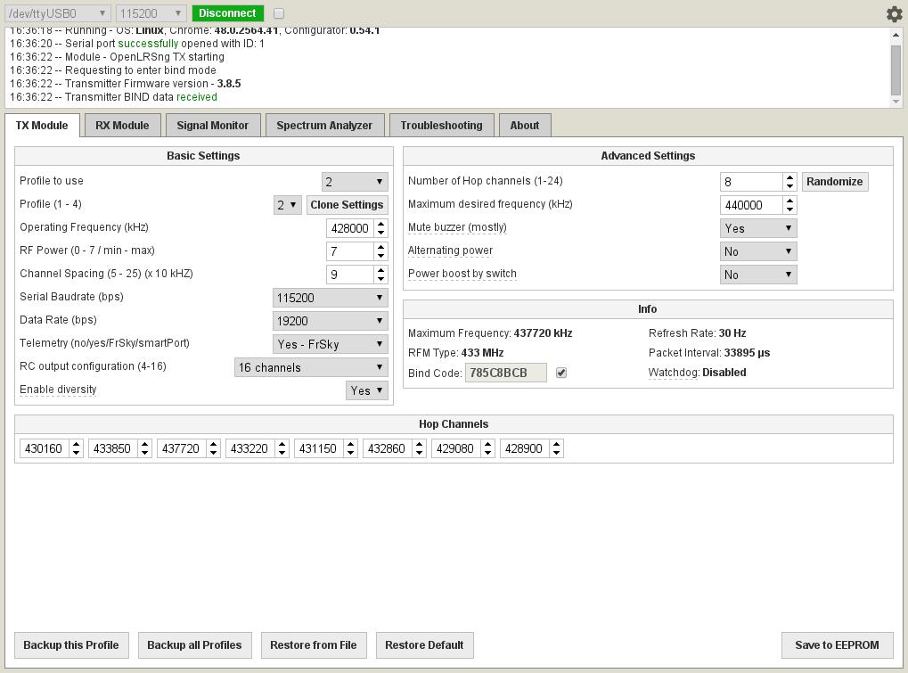
- RFM Type
- Select the frequency of the RF module on your device. Most units are 433.
- Operating frequency
- The lowest frequency of the frequency range you are transmitting (antennas let you veer away from 433Mhz, but the farther you go, the more you'll be losing range in an exponential fashion).
- RF Power
- The output power setting of the transmitter. 0 is the lowest and 7 is the highest. The receiver will use the same power setting if telemetry is enabled. 1W hardware should not be set to a value lower than 5. Power output does not change linearly with this setting.
Setting RFM22B(100mW) RFM23BP(3.3V) RFM23BP(5V) RFM23BP(6V) 100mW units Orange/Flytron Hawkeye/DTF some DIY 0 1.3mW N/A N/A N/A 1 1.6mW N/A N/A N/A 2 3mW N/A N/A N/A 3 6mW N/A N/A N/A 4 13mW N/A N/A N/A 5 25mW 350mW 500mW 630mW 6 50mW 450mW 650mW 800mW 7 100mW 600mW 800mW 1000mW - Channel spacing
- The amount of frequency between each channel. This can be used to get a list of channels between Min and Max desired frequency
- Serial baudrate
- The connection speed of the serial link if you are using the transparent serial link. This is only the connection speed, which will depend on the devices that you are connecting to. The rate that data can be sent will probably be much lower.
- Data rate
- The rate that data is sent between the transmitter and receiver. Lower numbers mean slightly improved range at the cost of servo refresh rate.
- Enable telemetry
- Enable the telemetry link from the receiver. The transmitter will beep if the receiver experiences packet loss. Also, the transparent serial bridge will be available. The FrSky option will enable FrSky telemetry output on the transmitter for connection to OpenTX or FLD-02. The Smartport option only supports telemetry and 2 analog back channels, it works but FrSky is preferable.
- RC output configuration (channels)
- Select the number of channels that will be sent to the receiver. This is also the number of channels that will appear on the receiver’s PPM output. Additional channels sent to the transmitter will be ignored. Example: if the transmitter is set to 8 channels, and you controller is set to 12 channels, only the first 8 channels will be sent to the receiver. The “Switch” channels are channels with very low resolution - only 4 positions; however they take 1/5th of the time to transmit, increasing the number of useful channels for a certain refresh rate.
- Enable Diversity
- This sends a longer pre-amble and is required if you use a module like the Brotronics Diversity RX
- Number of hop channels
- This will allow you to set the number of hopping channels. While it's tempting to use 24 for better protection from interference, too many channels mean that it takes longer to re-acquire a lost signal and/or bind. 8 is a good number to start with
- Maximum desired frequency
- Set the maximum frequency you want to transmit on. All the hopping channels will be placed below this frequency. Keep in mind again that the farther you get from 433Mhz, the less effective the antennas will become (going 10MHz on either side is ok though)
- Mute Buzzer
- As you fly farther away with a 1W TX and a 100mW RX, you will lose your telemetry back channel and the constant beeps from your TX module will become very annoying. This is where you turn them off :)
- Alternating Power
- Sends every Nth packet with lower power. This is meant to trigger LBEEPs and warn you that you're pushing your range. If you have a proper RSSI connection back to your OSD, you're unlikely to benefit from this though
- Power Boost by Switch
- If you set your RF power to 5 instead of 7, allows the switch to switch to 7 (full power). Unless you know why this is useful to you (like mostly flying short range and wanting to be a good RF citizen), you're likely better off keeping your TX power at 7 and not bother with boost by switch
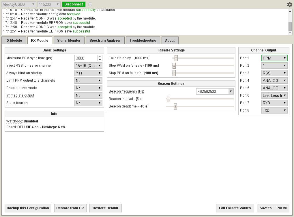
Receiver settings are set on each individual RX and stored in the RX's memory. The RX will keep these settings until they are changed or erased during a software update.
PPM output is available on one pin. It can be enabled by setting the correct port to output PPM. High-frequency RSSI / LBEEP is also available on one pin and is enabled the same way. See the Hardware Guide to find the correct port for your receiver.
- Minimum PPM sync time
- The minimum time between PPM frames on the PPM output. The default value works fine for many systems but fickle systems such as Ardupilot require a longer sync time (ardupilot 3.1 and better works ok with 3000, some older versions apparently want 4200).
- Inject RSSI on servo channel
- The RSSI signal is turned into an output that can drive a servo and injected into the PPM stream, replacing the RC channel of your choice. If you are connected to your flight controller via PPM/SBUS/SUMD/etc, you can reuse the existing cable to send RSSI instead of using a different output port on the RX and a 2nd cable, to send RSSI. Ardupilot 3.4 and better support RSSI over PWM (but if you connect via PPM, be careful that AP 3.4 does not currently see any channels past 12). See RSSI at the bottom of this page for more details on the 3 kinds of PWM RSSI.
- Always bind on startup
- By default, the receiver always listens for a bind message for a moment when power is applied. If this feature is disabled, you must jumper ports 1 and 2 to force the RX into bind mode on startup.
- Limit PPM out to 8 channels
- Some devices that accept PPM are also picky about the number of PPM channels that are in a PPM frame. This option is used to only output the first 8 channels in the PPM stream regardless of the number of channels sent to the receiver.
- Enable slave mode
- This option is for a future multi-RX diversity mode. Don't use it for now.
- Enable slave mode
- This option is for a future multi-RX diversity mode. Don't use it for now.
- Immediate output
- start outputting ppm/pwm using failsafe values befoero it gets first packet from tx. Unless you know you need this, this is probably not what you want (especially if it gives you partial motor power)
- static beacon
- By default, the 5 tone beacon that is sent after you lose signal has decreasing power output (useful to know that as you get closer, you start hearing more of the 5 tones). This setting disables that. Unless you know why you ned this, you probably don't want to enable it
- Failsafe delay
- The amount of time after the last packet is received before the receiver will load failsafe values. This can be used to “fly through failsafes” and can be adjusted to your liking. This value is in 1/10ths of a second.
- Stop PWM on failsafe
- Completely disable PWM outputs on failsafe.
- Stop PPM on failsafe
- Completely disable PPM outputs on failsafe.
- Beacon frequency
- If this option is enabled a tone is transmitted on the selected frequency that can be picked up using a common FRS, PMR or amateur radio walkie-talkie to aid finding a lost airplane or helicopter. Five tones are sent of descending transmit power to help you zero in on its location. The beacon is sent after failsafe has been activated.
- Beacon interval
- The amount of time the beacon will idle between transmit sequences.
- Beacon deadtime
- The amount of time after failsafe has been enabled before the beacon starts.
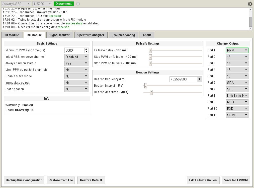
- Channel Output
- Set the outputs for each port in this menu.
As you'll likely see what's available on each pin depends on the pin and what RX hardware you have. Here are the available options:
- 1-16: Unmodified analog signal from TX
- S1-S16: send 0 or 3.3V depending on TX position (useful to activate a buzzer, LEDs, or other on/off devices)
- SDA/SCL: experimental, currently only used for diversity with 2 modules.
- Analog: selecting 2 ports as analog sends back their 0-3.3V value as analog channels that can be received by the TX
- link loss indicator: turns on if link is totally lost (useful for a buzzer)
- packet loss beeper: same thing but sends signal for each packet lost (early warning). Because this is shared with the pin that can do RSSI, you'll likely want RSSI if your OSD/flight controller supports it
- RSSI: digital or analog RSSI output (see below). Not needed if you are using inject RSSI on servo channel.
If you want to read about all these protocols, see: http://blog.oscarliang.net/pwm-ppm-sbus-dsm2-dsmx-sumd-difference/
PPM is the basic option. But if you want 16 channels on ardupilot or your flight controller doesn't support CPPM/PPMSum, you have more options, however they unfortunately take over the pin that does Serial TX and they also change the baud rate of the single UART in the module, which will affect the speed of the RX pin in the other direction. In other words, if you want to serial passthrough, you will want to stick with PPM.
Here's the list:
This works in most cases (up to 12 channels if you use ardupilot, see https://github.com/diydrones/ardupilot/issues/3337 ). This is your simplest option if supported, and does not take your TX pin like the other options
On most hardware, this is actually inverted SBUS because a normal UART cannot output real SBUS. If you are using ardupilot and want 16 channels, don't bother with inverted SBUS and try SUMD instead. But if you need SBUS, see this page to make an inverter: http://www.rcgroups.com/forums/showthread.php?t=1459431&page=2 and https://groups.google.com/forum/#!msg/px4users/gUE6mPISvKA/aiaC6XwvJckJ . If you are lucky to have an RX module like the Broversity RX, port 11 is mapped to the TX pin, and the SBUS pin inverted, so you actually get real working SBUS (which requires hardware inverted serial) that can be plugged directly into a pixhawk. Also note that SBUS is not scaled the same, so your endpoints will be different than with other protocols (see http://www.rcgroups.com/forums/showpost.php?p=33100808&postcount=8082)
Spektrum satellite input. This plugs into a pixhawk sbus input, however you should only wire the Signal (1) and Ground (2) pins, and wire the red wire (5V) to a servo output on your pixhawk (the spektrum input Pin3 only gives 3.3V). Wiring of the spektrum plug on pixhawk is Signal/Gnd/3.3V (from left to right) with writing pointing up
It's a better protocol than Spektrum and supports 16 channels natively instead of 7+7 (14) in alternating frames for Spektrum. Ardupilot supports SUMD on the Spektrum port, so you should use this. Again, only wire Pin1 (signal), Pin2 (Ground) on the spektrum plug, and route the Vcc wire to a 5V output on the pixhawk (SBUS port, or servo output). This is your best protocol that passes through 16 channels to a pixhawk if you can't use SBUS with an inverter (built in, or not)
- 1: (C)PPM / PPMSum
- 2: SDA/analog
- 3: RSSI / packet loss beeper
- 4: SCL/analog
- 5: analog
- 6: Analog / link loss indicator
- 7: RXD
- 8: TXD / Spektrum / Inverted SBUS / SUMD
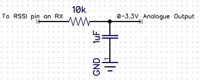
There are 3 different RSSI modes available in openLRSng:
Some modules only output digital RSSI, so the high-frequency signal should be filtered to produce an analogue signal which is expected by most OSDs/flight controllers. Some modules have an on board jumper you need to solder to output analog RSSI directly without need for an external filter (on DTF UHF 4-channel receivers V2 and newer, the filter is on-board and can be enabled by soldering a jumper as seen in the Hardware Guide). An external filter can be made with a capacitor and resistor.
This will output a beep on a lost radio packet that continues until a valid packet is received. This output can be connected directly to the audio input of a video transmitter. Thus, instant audio feedback of the radio link quality is enabled. You can also use a link loss beeper output instead which will only turn on after link has been fully lost. Using LBEEP (link loss beep over FPV audio)
A RC servo channel can be replaced with RSSI information, and set to an output port to drive a servo or OSD with 50Hz servo-pwm. Note that this injection will replace that servo channel, or you can map this to an additional RC channel not used by your servos and not overwrite a PPM channel you are using. RSSI as a PWM channel is supported by Ardupilot 3.4 and above, but it does not seem to support reading any channels past 12 when you use PPM output, so don't use channels past 12 unless you're using SUMD or SBUS.
You can select 4 kinds of RSSI injection:
- RSSI: normal RSSI
- Qual: link quality, success rate of last 15 packets
- Comp: mix of rssi+qual
- Qual on port X, and RSSI on port X+1 Whether it makes sense to have Qual + RSSI (using 2 channels) or Comp (using one channel) is for you to find out :)
If you're curious, you can see the list of options available here: https://github.com/openLRSng/openLRSng-configurator/blob/master/tabs/rx_module.html