PID/FOC Custom Firmware for B-G431B-ESC1 board.
Follow us on Hackaday.io : https://hackaday.io/project/177578-b-g431b-esc-brushless-servo-controller
- 16KHz motor PWM
- 20KHz motor PWM
- Open-loop and closed-loop FOC algorithm (16KHz)
- Faster loop for FOC algorithm (20KHz)
- FOC with CSVPWM algorithm
- FOC with Field-Weakening (work in progress)
- Torque and Flux control (P only), with current limiter
- Position control with min/max position limiter (4KHz)
- Velocity control with max velocity limiter (4KHz)
- Torque and Flux feed-forward
- Auto-calibration of electrical angle and motor rotation
- USB control interface : dynamixel like protocol allowing full-access to control (RAM) and configuration (EERPOM)
- CAN control interface : variable-size control frames (RX) and feedback frames (TX), with fail-safe on bus time-out
- Power supply voltage monitoring, with min/max operating voltage (user configurable)
- Position sensor monitoring, with fail-safe on system error and bus time-out
- Temperature monitoring, with fail-safe on maximum temprature (user configurable)
- GUI Tool for configuration and test

Product page : https://www.st.com/en/evaluation-tools/b-g431b-esc1.html
Cost: approx. 18$ per unit.
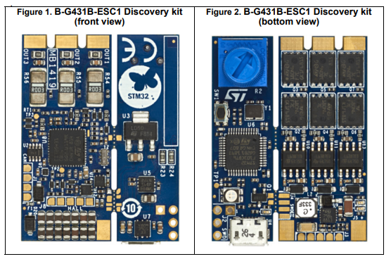
As mentioned in the user manual, the B-G431B-ESC1 Discovery kit is equipped with a USB connector and different pads for communication, such as:
- U4 USB port for programming and debugging
- J1 for CAN port
- J2 for SWD-STM32F103 (reserved)
- J3 for PWM/UART/BECout input/output signal
- J4 for SWD-STM32G431 debug/programming port (without daughterboard)
- J5/J6 for Lipo battery (30V or 6S max)
- J7 for motor
- J8 for motor sensor (Hall or encoder)

The USB interface is provided on the daughterboard and it allows to program and debug the main board. It provides also the supply voltage to the STM32G431CB MCU in case of no voltage on the bus (J5 and J6 not connected to the LiPo battery).
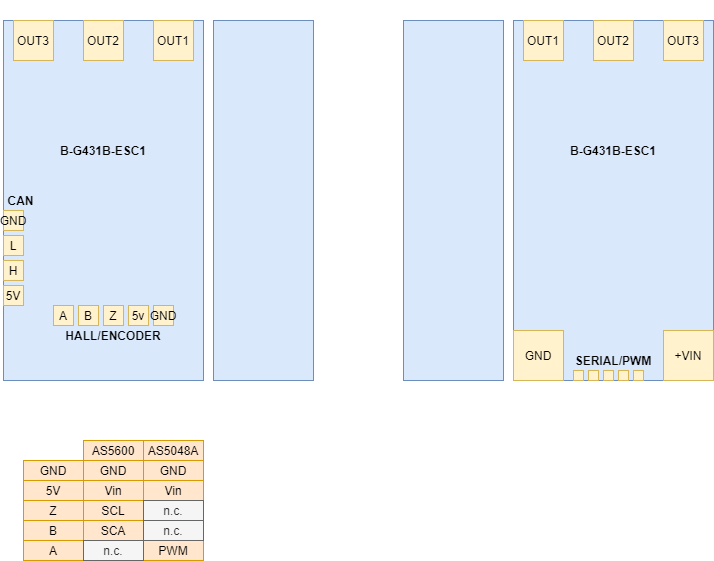
For proper operation of the FOC firmware, the J1, J5, J6, J7, an J8 solder pads should be connected. The J2, J3, J4 solder pads may be left unconnected.
For J8, the firmware accept two types of position sensor :
- The AS5600 Position Sensor connected through I2C port (https://ams.com/as5600)
- The AS5048A High-Resolution Position Sensor connected through PWM interface (https://ams.com/as5048a)
A full erase of the Chip is strongly recommended, to insure proper initialisation of the default configuration (the last Flash page stores PID/FOC configuration).
The release configuration of the PID/FOC firmware should be built with CubeIDE, and then uploaded using the USB port of the board.
A hard-coded setting must be adjusted by user, according its hardware configuration :
At lines 40+ of main.c,
// Position sensor type :
//    "AS5600_I2C"
//    "AS5048A_PWM"
#define SENSOR_TYPE AS5048A_PWM
The Red STATUS LED is normally OFF.
When an hardware error occurs, the LED is ON.
User may set the LED ON through USB interface.
A short press on the button starts the calibration sequence. It last a few seconds and the motor turns slowly. Rotor should be free to get a good calibration.
Notice : The number of pole pairs should be configured before starting the calibration sequence. User may set the pole pairs by connecting the ESC to a computer through USB and running the GUI tool.
GUI Tool allows to configure and to command the controller.
Connect the ESC to USB port, and change the line 20 in SBSUtility.py according serial device:
## change COM port here
servo = servo_protocol2('COM3',1000000)
Run SBSUtility.py

By default, the controller has the ID:1 and USB/VCP baud rate is 1Mbps.
Warning (wear) : Each time a value of an EEPROM register is changed, the Flash is reprogrammed. The number of programming cycles is approx 10.000 to 100.000.
| Field | Default Value | Description |
|---|---|---|
| ID | 1 | ID of the controler (used for both USB and CAN). Values: 000h < ID < 010h |
| Min Position | 0 | Minimum position in degress, limiting position control |
| Max Position | 1000 | Maximum position in degrees (position control) |
| Max Velocity | 5000 | Maximum velocity in degrees per second (velocity control) |
| Max Current | 500 | Maximum motor current in mA (FOC) |
| Max Temperature | 60 | Maximum operating temperaturein °C. Values: <70 |
| Min Voltage | 6 | Minimum operating power supply voltage. Values: <30 |
| Max Voltage | 28 | Maximum operating power supply voltage. Values: <30 |
| Encoder Resolution | 14 | Resolution of the position sensor in bits. Values: 12 for AS5600, 14 for AS5048A |
| Motor Pole Pairs | 14 | Pole pairs of the motor |
| Motor Synchro Angle | 0 | Offset in degrees between physical and electrical angles. Updated by auto-calibration |
| Motor Phase Inv | 0 | Motor phase inversion. Values: {0,1} Updated by auto-calibration |
| Field Weakening K | 255 | Field weakening. Values: 255 |
| PID Flux current KP | 400 | Kp of Flux PI FOC. |
| PID Torque current KP | 400 | Kp of Torque PI FOC. |
| Field | Default Value | Description |
|---|---|---|
| LED | 0 | STATUS LED ON/OFF command. Values: {0:OFF,1:ON} |
| Control Mode | 0 | Operating mode. Values: {0:IDLE,1:Position/VelocityTorque control} |
| Goal Position | 0 | Goal position in degrees (position control) |
| Goal Velocity | 0 | Goal velocity in degrees per second (velocity control) |
| FF Torque Current | 0 | Feed-forward torque current in mA (FOC, Iq) |
| Goal Flux Current | 0 | Reference flux current in mA (FOC, Idref) |
| Position Kp | 0 | Kp of Position/Velocity control. Values: 0<Kp<255 |
| Velocity Kd | 0 | Kd of Position/Velocity control. Values: 0<Kp<255 |
Warning : A high value of Kp or Kd may damage the actuator.
The controller accepts CAN frame identifier = 000h + its own ID (user configurable ID).
The controler repies with CAN frame identifier = 010h + its own ID (user configurable ID).
At start-up (power-on reset), the controller is in IDLE state (motor brake). The position and velocity set-points, the current feed-forward and the Kp and Kd are reset (=0).
In order to arm the controller, a full control frame with a 0xFFFFFFFFFFFFFFFF payload should be sent. The velocity set-point, the current feed-forward and the Kp and Kd are reset (=0). The position set-point is set to the present rotor position.
To disarm the controller, a full control frame with a 0x000000000000000 payload should be send. The position and velocity set-points, the current feed-forward and the Kp and Kd are reset (=0).
The controller disarms it-self automatically, when a CAN bus time-out occur (no control frame received for one second). The position and velocity set-points, the current feed-forward and the Kp and Kd are reset (=0).
For 16-bit fields, low byte first position, high byte second position.
A full control frame has a 64-bit payload.
| Field | Length | Value |
|---|---|---|
| Position | 16b | Position set-point in 1/10 degrees |
| Velocity | 16b | Velocity set-point in degrees per second |
| Torque | 16b | Torque current feed-forward in mA |
| Kp | 8b | Position control |
| Kd | 8b | Velocity control |
Warning : A high value of Kp or Kd may damage the actuator.
A 48-bit control frame contains :
| Field | Length | Value |
|---|---|---|
| Position | 16b | Position set-point in 1/10 degrees |
| Velocity | 16b | Velocity set-point in degrees per second |
| Kp | 8b | Position control |
| Kd | 8b | Velocity control |
A 32-bit control frame contains :
| Field | Length | Value |
|---|---|---|
| Position | 16b | Position set-point in 1/10 degrees |
| Velocity | 16b | Velocity set-point in degrees per second |
A 16-bit control frame contains :
| Field | Length | Value |
|---|---|---|
| Torque | 16b | Torque current feed-forward in mA |
A 32-bit feedback frame contains :
| Field | Length | Value |
|---|---|---|
| Position | 16b | Present position in 1/10 degrees |
| Torque | 16b | Present torque current in mA |