Was Standard for serial communication
Used for communication with printer, mice. Today mostly succeeded by USB.
Today still used for service config ports and PRS communication.
Asynchronous data transfer ASCII coded
- Speed: dependend on interface, normally 1.5 Mbit/s
- Length:
- Standard: 15m
- Low capacity: 300m
Low speed bus for connection of peripherals to microcontrollers Invented by Philips.
- Wiring:
- USDA: data
- Clock: USCL
- 5V or 3,3V
- 10kbit/s - 3.5Mbit/s
- Length a few meters
Both lines address room of 7 bit
Half duplex protocol.
- Examples: read EEPROM, access DAC, control OLED or LCD ARDUINO, Linux, Mac, Windows
- Speed: Faster than other 2 before, no speed specification found
- Wiring:
- clock
- master in / slave out
- master out/ slave in
- slave select
- Lenght: short distance, about 3m
Synchronous, Master Slave
Full Duplex.
Microcontrollers that communicate with peripherals.
Similar to I²C but with lower data rate and longer range.
- Wiring: only two wires: data and ground
- Speed:
- 16.3 kbbit/s
- 10x the speed in overdrive mode
- Max Length: 750m
Typically used for power signalling for small, inexpensive devices (digital thermometers, weather instruments).
A network of Onewire devices with associated master is called MicroLAN.
1-Wire devices include an 800 pF capacitor to store charge, and to power the device during periods when the data line is active.
Uses the 1-wire protocol
- Examples: Java Ring, iButton, Apple MagSafe for Powersupplies
- measures 9bit to 12bit temperature values in celsius (-55°C to +125°C)
- Power supply range from 3.0V to 5.5V
- User-defined alarms (low and high temperature value for alarm)

- Low power operation
- 1.71 V to 3.6V supply operation
- 29 uA supply current at 16 ms sampling interval periods
- 3 uA Stop mode current
- 12 capacitance sensing inputs
- 8 Inputs are multifunctionla for LED driver and GPIO
- Complete touch detection
- Auto-configuration for each sensing input
- Auto-calibartion for each sensing input
- Touch/release threshold and debounce for touch detection
- I²C interface, with interrupt output
- 3mm x 3mm x 0.65 mm 20 lead QFN package
- -40°C to + 85°C operating temperature range
Connect Raspberry Pi 3.3V to MPR121 VIN. Connect Raspberry Pi GND to MPR121 GND. Connect Raspberry Pi SCL to MPR121 SCL. Connect Raspberry Pi SDA to MPR121 SDA.

- How to Wire
KY-004 -> Arduino
S -> e. g. Pin 10
- + (middle) -> +5V
- - -> GND


-
What to measure/trigger/threshold
- Outputs a high-signal when pressed
-
Example:
---------------------------------------
EXAMPLE
Will turn on Arduino's pin 13 LED when button on KY-004 is pressed
---------------------------------------
int Led = 13 ;// define LED Interface
int buttonpin = 10; // define the key switch sensor interface
int val ;// define numeric variables val
void setup ()
{
  pinMode (Led, OUTPUT); // define LED as output interface
  pinMode (buttonpin, INPUT); // define the key switch sensor output interface
}
void loop ()
{
  val = digitalRead (buttonpin); // digital interface will be assigned a value of 3 to read val
    if (val == HIGH)  // When the key switch when the sensor detects a signal, LED flashes
  {
    digitalWrite (Led, HIGH);
  }
  else
  {
    digitalWrite (Led, LOW);
  }
}
- low cost 6$
- low power (2V to 5.5V)
- capacitance (0-50uF)
- sensitivity adjustable
- response time: 60ms (fast) - 220ms (low)
- 2 modes:
- low power = 1.5uA - 3.0uA
- fast mode = 3.5uA - 7.0uA
- wiring: 3 pins: power (vcc) ,ground (gnd), output monitor (sig)
- arduino:
- sig to digital
- vcc to 5V
- gnd to gnd
- pins:
- capacitive touch pin = 2 (input) - when input high = touched
- led pin = 13 (output) - when output high = led lit (can also be inverted to when output low = led lit)

The Grove - Gas Sensor (MQ2) module is useful for gas leakage detection (home and industry). It is suitable for detecting
- H2
- LPG
- CO
- Alcohol
- Smoke or Propane
Due to its high sensitivity and fast response time, measurement can be taken as soon as possible. The sensitivity of the sensor can be adjusted by potentiometer.
The sensor value only reflects the approximated trend of gas concentration in a permissible error range, it does not represent the exact gas concentration. The detection of certain components in the air usually requires a more precise and costly instrument, which cannot be done with a single gas sensor.
Featues:
- Wide detecting scope
- Stable and long lifetime
- Fast response and high sensitivity
This is an analog output sensor. It needs to be connected to any one analog socket in Grove Base Shield. It is possible to connect the Grove module to Arduino directly by using jumper wires. The output voltage from the Gas sensor increases when the concentration of gas increases.
- High sensitivity to carbon monoxide
- They are used in gas detecting equipment for carbon monoxide(CO) in family and industry or car.
- The standard measuring circuit of MQ-7 sensitive components consists of 2 parts. One is heating circuit having time control function (the high voltage and the low voltage work circularly). The second is the signal output circuit, it can accurately respond changes of surface resistance of the sensor.
- The MQ7 has 6 pins. 4 of them are used to fetch signal and the other two are used for heating current.
Connections:
- +5V
- DOUT Digital OUT
- AOUT Analog OUT
- GND
Sensor lead analog output AOUT and a digital output DOUT. The higher the analog voltage level the higher the alcohol the sensor detects. If the analog voltage reaches a certain treshold the DOUT is set to HIGH. This HIGH can be detected by the arduino.
AOUT is connected to an analog pin of the arduino. With analogRead the alcohol value can be read from the sensor. DOUT is connected to a digital pin of the arduino. If the digital Read detects a HIGH the alcohol level is to high and a LED could be triggered to show that the limit is reached.
Details:
- advanced digital light sensor, ideal for use in a wide range of light situations
- more precise than low cost CdS cells
- exact Lux calculations
- different gain/timing ranges
- light ranges 0.1 - 40.000+ Lux
- contains infrared and full spectrum diodes
- seperatly measure infrared, full-sprectrum and human-visible light
Interface:
- digital I2C interface
- select one of three addresses -> up to three sensors on one board each with different I2C address
- built in ADC makes compatible with any microcontroller
- low power usage, great for low power data-logging systems
- 0.5mA when active, less than 15 uA when in powerdown mode
Stats:
- Approximates human eye response
- precisely measure illuminance in diverse lighting conditions
- -30 to 80 °C
- 0.1 to 40.000 Lux
- 2.7-3.6V
- I2C interface
Wiring up the sensor:
- Connect the VCC pin to a 3.3V or 5V power source
- Connect GND to the ground pin
- Connect the i2c SCL clock pin to your i2c clock pin (Classic Arduino -> Analog pin #5)
- Connect the i2c SDA data pin to your i2c data pin (Classic Arduino -> Analog pin #4)
- Dont need to connect the ADDR or INT pins
- ADDR can be used if you have a i2c conflict
- INT pin is an output from the sensor used when the sensor is configured to signal when the light level changes (if used -> 10K to 100K pullup from INT to 3.3V vcc)
Using the sensor:
- Math datasheet http://learn.adafruit.com/tsl2561/downloads
- Arduino library repo on github http://adafru.it/aZ9 and guide http://learn.adafruit.com/adafruit-all-about-arduino-libraries-install-use
- Ardafruit V2 library https://github.com/adafruit/Adafruit_TSL2561/archive/master.zip
- Adafruit standard library https://github.com/adafruit/Adafruit_Sensor
- Adafruit sensor library https://github.com/adafruit/Adafruit_Sensor/archive/master.zip
- Restart IDE
- Run File>Examples>Adafruit_TSL2561>sensorapi
- Open serial monitor at 9600 baud to see measurements
The rain water sensor has a dry working voltage of 5V. As rainwater falls onto it, the exposed wires are bridged and the output gradually becomes less. It is an analog sensor, and the amount/strength of the rain can be determined by analysing the analog output. Wiring: The sensor needs 5V of power to work, the + pin is connected to the corresponding + pin on the sensor board, and the – pin is connected to the corresponding – pin on the sensor board. Needs A/D Converter
- analog signal with value
- 0mm - 480
- 5mm - 530
- 10mm - 615
- 15mm - 660
- 20mm - 680
- 25mm - 690
- 30mm - 700
- 35mm - 705
- 40mm - 71
Precision 24-bit analogto-digital converter (ADC) designed for weighscales and industrial control applications to interface directly with a bridge sensor. Two selectable differential input channels On-chip active low noise PGA with selectable gain of 32, 64 and 128 On-chip power supply regulator for load-cell and ADC analog power supply Digital control and serial interface: pin-driven controls, no programming needed Operation supply voltage range: 2.6 ~ 5.5V Channel A can be programmed with a gain of 128 or 64, corresponding to a full-scale differential input voltage of ±20mV or ±40mV when 5V supplied on AVDD
Pin description
- 1 VSUP Power Regulator supply: 2.7 ~ 5.5V
- 2 BASE Analog Output Regulator control output(NC when not used)
- 3 AVDD Power Analog supply: 2.6 ~ 5.5V
- 4 VFB Analog Input Regulator control input(connect to AGND when not used)
- 5 AGND Ground Analog Ground
- 6 VBG Analog Output Reference bypass output
- 7 INA- Analog Input Channel A negative input
- 8 INA+ Analog Input Channel A positive input
- 9 INB- Analog Input Channel B negative input
- 10 INB+ Analog Input Channel B positive input
- 11 PD_SCK Digital Input Power down control (high active) and serial clock input
- 12 DOUT Digital Output Serial data output
- 13 XO Digital I/O Crystal I/O (NC when not used)
- 14 XI Digital Input Crystal I/O or external clock input, 0: use on-chip oscillator
- 15 RATE Digital Input Output data rate control, 0: 10Hz; 1: 80Hz
- 16 DVDD Power Digital supply: 2.6 ~ 5.5V
Pin PD_SCK and DOUT are used for data retrieval, input selection, gain selection and power down controls.
Output The output 24 bits of data is in 2’s complement format. When input differential signal goes out of the 24 bit range, the output data will be saturated at 800000h (MIN) or 7FFFFFh (MAX), until the input signal comes back to the input range
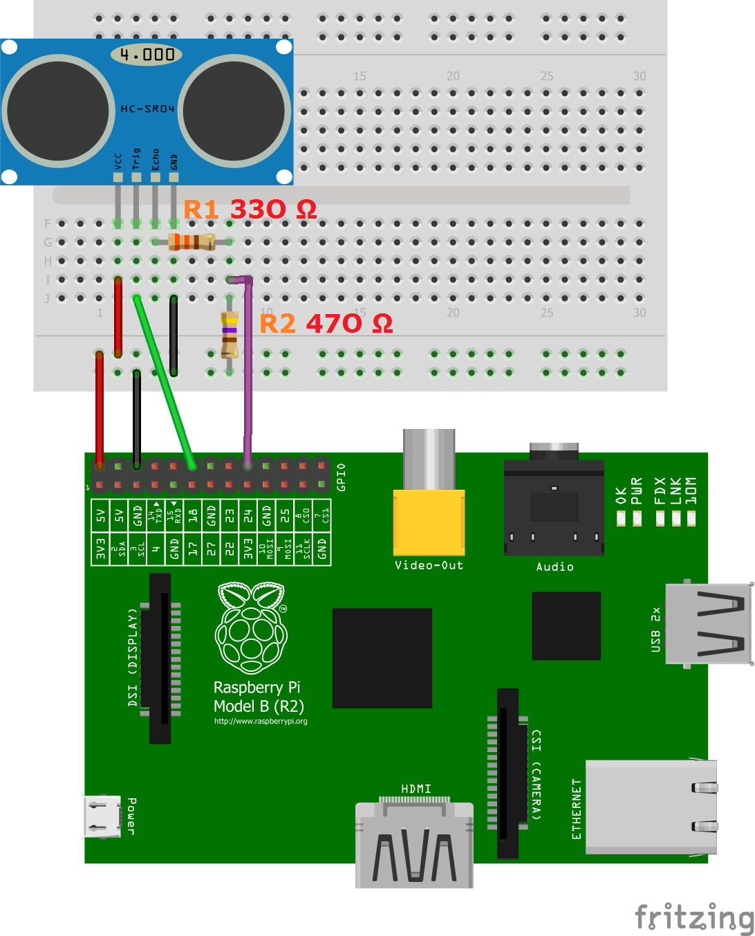
The HC-SR05 has 5 pins (left to right):
- VCC
- Trig
- Echo
- GND
There are four pins on the ultrasound module that are connected to the Raspberry:
- VCC to Pin 2 (VCC)
- GND to Pin 6 (GND)
- TRIG to Pin 12 (GPIO18)
- Connect the 330Ω resistor to ECHO. On its end you connect it to Pin 18 (GPIO24) and through a 470Ω resistor you connect it also to Pin6 (GND).
We do this because the GPIO pins only tolerate maximal 3.3V. The connection to GND is to have a obvious signal on GPIO24. If no pulse is sent, the signal is 0 (through the connection with GND), else it is 1. If there would be no connection to GND, the input would be undefined if no signal is sent (randomly 0 or 1), so ambiguous.
Send a 10 uS wide pulse to the sensor on the Trigger Pin.
The sensor will automatically send out a 40 kHz wave.
Begin monitoring the output from the Echo Pin and when the Echo Pin goes high, begin a timer.
When the Echo Pin goes low, record the elapsed time from the timer and use the following conversion formula:
Distance (in cm) = (elapsed time * sound velocity) / 100 / 2
Note:
- Divide distance by 2 because the sensor returns the round trip time, which doubles the distance measurement.
- sound velocity(340 m/s)
For Arduino UNO and NANO
- Pin A4(SDA) and A5(SCL)
- External Power Supply 5V (Ground to Arduino)
- For finding the I2C address the scanner from Arduino-Playground is a nice to use
- Adafruit Libraries commonly used to get things done:
- SSD1306
- GFX
- Connections from the display:
- VCC to external 5V
- GND to external GND
- SCL to Arduino Pin A5(SCL)
- SDA to Arduino Pin A4(SDA)
- Arduino GND Pin to external pus GND
- Arduino connected to PC via USB cable (Power)
- Voltage: 12 V
- Current: 350 mA
- Unlock time: 1 second
Since the voltage and the current is that high (most microcontrollers don't support that), you need to have an external voltage supply. This can be switched either with an
- Transistor (really depends on the transistor)
- Mosfet
- Relay
- Red wire connects to positive, green to negative
- When it has been connected and current is available, the door is open - otherwise it is closed
Each pixel of the three primary color can achieve 256 brightness display Brightness and color of each LED can be individually controlled Each LED has a IC built right into the LED, serial connected Therefore you just need one digital data ping
- Connect a capacitor with a capacitance between 100uF and 1000uF from power to ground to smooth out the power supply.
- Add a 220 or 470 Ohm resistor between the Arduino digital output pin and the strip data input pin to reduce noise on that line.
- Make your wires between the arduino, power supply and the strip as short as possible to minimize voltage loss.
- If your strip gets damaged and doesn’t work, check if the first LED is broken. If so, cut it, resolder the header pins, and it should be working again.
- Install the FastLED library
https://randomnerdtutorials.com/guide-for-ws2812b-addressable-rgb-led-strip-with-arduino/

- GPIO 18 for data
https://tutorials-raspberrypi.de/raspberry-pi-ws2812-ws2811b-rgb-led-streifen-steuern/

Allows precise control of angular and linear position, velocity and acceleration.
- Robotics
- CNC
- Automated Manufacturing
In comparison to the stepper motor, a servomotor does only consume power, while it moves to the designated location, then it rests.
Connections: PWM VCC Ground
Position can be changed by sending a pulse to the PWM connection Example for SG90: 1ms -> -90° 1.5ms -> 0° 2ms -> 90° The servomotor expects a pulse every 20ms Dead band with: 20µs (Time which will be ignored if signals are shorter than that, for e.g. filtering noise) The servo then will stay in this position. If an external force is applied, the so called torque rating is how much force the servo can resist before moving.
Operating voltage: 4.8V (~5V)