Interfacing Arduino with 13.56MHz ISO14443 RFID tags using NXP MFRC522 reader modules
By default, these readers use the SPI interface, although the chip also supports UART and I2C. Datasheet can be found here. For a comparison of alternative readers, see https://www.patreon.com/posts/rfid-roundup-23115452
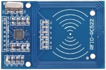
There are 8 pins on the MFRC522 board, as follows:
- SDA : Serial Data (I2C mode) / (Not) Slave Select (SPI mode) is pulled LOW when communicating with Arduino *
- SCK : System Clock signal sent from Arduino *
- MOSI : Master-Out, Slave-In used for transmitting data from Arduino to the reader *
- MISO : Master-In, Slave-Out used for transmitting data from the reader to the Arduino
- IRQ : Not required
- GND : Ground
- RST : Reset line from Arduino *
- +3.3V : +3.3V DC supply
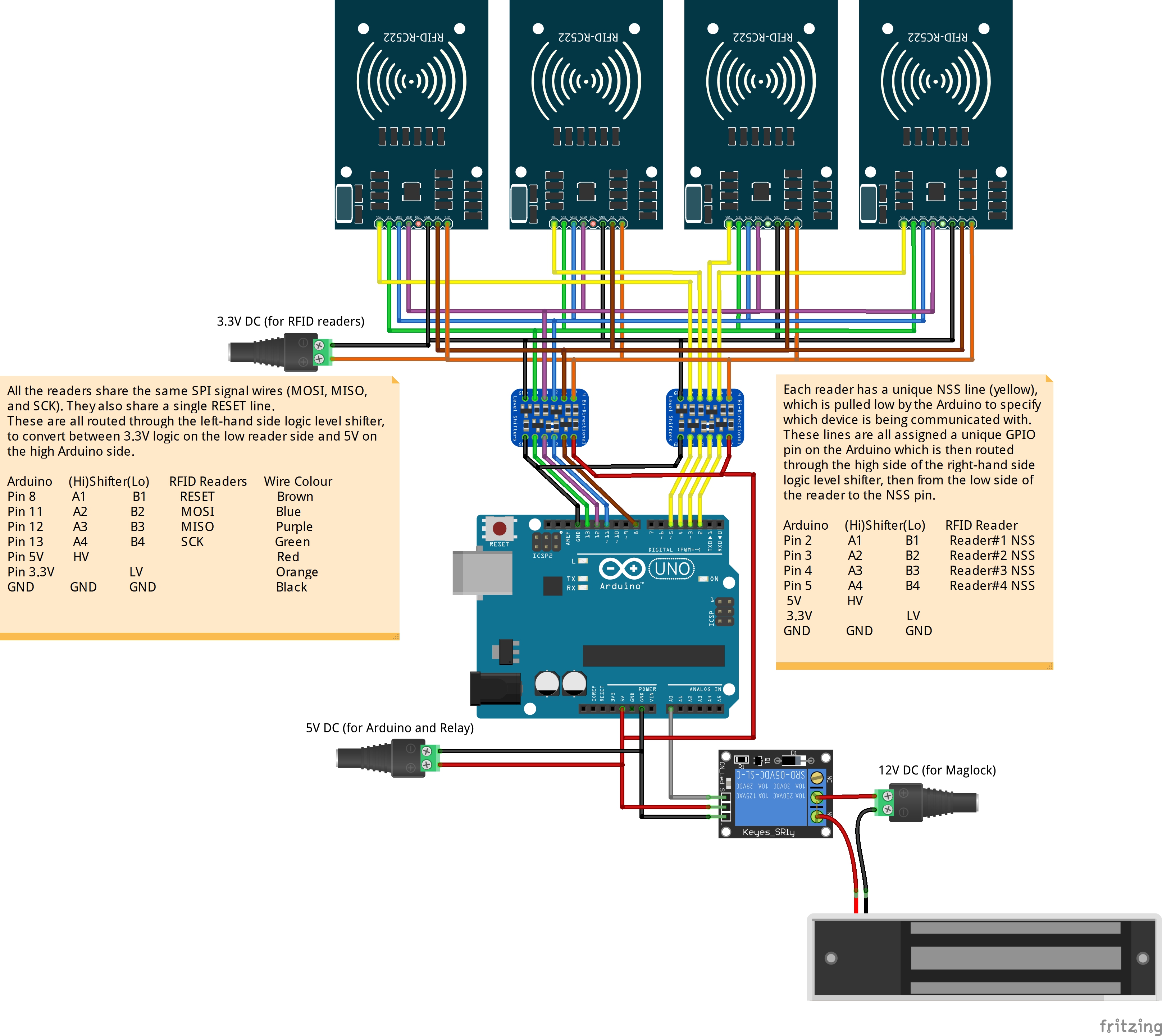
Arduino UNO/Nano/Mega operates at 5V logic. However, the MFRC522 works at 3.3V logic level, and is not 5V tolerant. If using one of these microprocessors:
- You must use a 5V <-> 3.3V level shifter on any lines that send HIGH output from the Arduino to the MFRC522. These are RST, NSS, MOSI, and SCK marked with an asterisk in the list above.
- You may use a 3.3V <-> 5V level shifter on those lines that send HIGH output from the MFRC522 to the Arduino (MISO) though this is not generally necessary - a HIGH 3.3V signal will normally be recognised as a HIGH signal on a 5V system too.
- But, while logic level shifters solve the problem of interfacing between devices at different voltages, they can introduce other problems... simple bi-directional convertors use transistors that can be slow to react, and this delay damages the timing and quality of the signal. This can be mitigated somewhat by explicitly slowing down the speed of the SPI interface in the Arduino code, by including #define MFRC522_SPICLOCK (400000u) (Sets SPI bus to 400kHz) prior to including the RFID library.
- MOSI, MISO, and SCK lines are shared between all readers, and use Arduino SPI pins 11(MOSI), 12(MISO), and 13(SCK).
- NSS lines must be assigned to unique GPIO pins for each reader.
- Some cheap boards are known to not properly release the MISO line when deselected. For those boards, it is recommended to either place a buffer or multiplexer to expicitly disconnect that line from noise of unselected chips.
Mistakes people make:
a.) Not using correct logic voltage
Some sites claim "the good news is that the logic pins are 5-volt tolerant" (e.g. https://lastminuteengineers.com/how-rfid-works-rc522-arduino-tutorial/)
There is absolutely nothing in the datasheet to suggest this is the case. The limiting values are shown in Table 150 of the MFRC522 spec at https://www.nxp.com/docs/en/data-sheet/MFRC522.pdf#G1001030350 4::
VI, Input Voltage on all pins V: VSS - 0.5 < VI < VDD + 0.5
Given VSS/VDD(max) = 4.0V, if you supply 5.0V on any MOSI/MISO/CLK or RST SPI pins, you’re outside the maximum… See https://forum.arduino.cc/t/5v-pro-mini-and-rc-522-rfid/388666/19
b.) Using a (poor) logic level convertor If the MFRC522 is not 5V tolerant and you want to use a 5V Arduino, you simply need to add one of those bi-directional logic level convertors (like this: https://www.sparkfun.com/products/12009), right? Wrong! The irony is that while these convertors fix the problem of voltage, they introduce new problems with timing - the rising and falling edge are often missed. See https://forum.arduino.cc/t/rc522-not-working/892388/8 CLK and MOSI lines carry 5V signals going into a 3V3 device so you should convert them with a 510R and 1K resistor. "Bidirectional logic convertors" are often too slow for SPI communication. So, the irony is that you introduce them to fix problems with the data lines being the wrong voltage, but then introduce new problems with timing. It can also help to explicitly reduce the speed of the SPI bus declared in the <a href"https://www.arduino.cc/reference/en/language/functions/communication/spi/spisettings/">SPISettings.
The solution to both a.) and b.) is trivially to use a 3.3V microprocessor rather than a 5V Arduino. e.g. An ESP8266 or ESP32
c.) Not supplying enough power The 3.3V output from the Arduino is not capable of supplying much power - it is only good for up to ~150mA. If powering several RFID readers you must use a separate appropriately rated 3.3V supply (budget for ~100mA per reader). From the datasheet: "During operation with typical circuitry, the overall current is below 100mA"
Problems resulting from using multiple readers on the same SPI bus:
d.) Increased capacitance due to all the extra wiring SPI interface is designed to run between components on a PCB, not for long wire runs between devices. Keep cables as short as possible, preferably 20cm or less.
e.) Some clone readers do not respect SS signals and/or do not tri-state MISO line when not selected Discussed in investigations below.
If you're going to connect a lot of readers, you will probably end up using a multiplexer to select the appropriate reader. If that's the case, you may as well also use the same control lines to also switch the SCK, MISO, and MOSI lines. That way, you're not really using a "bus" at all - you're connecting each reader in isolation, so they can't possibly interfere with each other. Even better, you don't get the additional capacitance on the line, because the additional wiring is essentially disconnected!
There is a suggestion that the chip does not properly tri-state the MISO line.
https://arduino.stackexchange.com/questions/18313/issue-sharing-miso-with-multiple-rc522-rfid-readers suggests a solution which is set out here: SS GND MISO GND 0.4V signals SS GND MISO 3.3V 0.56V signals SS 3.3V MISO GND 0V SS 3.3V MISO 3.3V 3.3V
Another investigation described at https://www.pjrc.com/better-spi-bus-design-in-3-steps/ "When all SPI chips are disabled, the MISO signal should “float” to approximately half the Vcc voltage." It does, exactly! 1.65V
This comment on a YouTube video suggests that the problem with the MISO line is that it is too weak https://www.youtube.com/watch?v=ahc8Yai_sWI&lc=Ugx-FXXT6SMyXuiPKel4AaABAg Some people all over the internet face issues when connecting multiple RFID boards in parallel to Arduino board. When 2+ readers connected it stop working. One reader works perfectly but 2+ pcs. not. The problem is weak MISO output of some reader board. Checked some Russian electronics forums and found answer how to make multiple readers work. You need to connect MISO outputs through the OR logic gate to Arduino. It is possible to use logic OR IC chip or just simple diodes+resistor OR element. Connect anodes of diodes to MISO reader outputs. Then tie all cathodes together, put 4k7 resistor to the ground (yeah we just built OR logic gate) and then connect to the MISO pin 12 (on Arduono Uno). That's it! Tested with 3 readers. Work like ice ;)
Long wire runs in SPI buses introduce issues of resistance, capacitance, and inductance... https://electronics.stackexchange.com/questions/594740/spi-noise-after-extending-wires-why
SPI ultimately not built for noise immunity! Best to place a separate MCU on each board and connecting them via CANbus https://electronics.stackexchange.com/questions/33125/short-distance-board-to-board-communication https://www.reddit.com/r/arduino/comments/xnumjp/connecting_20_rfid_readers_to_arduino_uno_and/
People have tried to hold the RESET line low to disable devices instead of using the SS line. miguelbalboa/rfid#290 This works, but behaviour is not correct - according to the datasheet, when RST is low the output on the MISO line can be held HIGH or LOW - we want it to be Z.
Place a series resistor in the SPI lines near the driver to reduce ringing and reflections. This should have the same resistance as the impedance of the trace/wire Try a value of about 50ohm. https://electronics.stackexchange.com/questions/594740/spi-noise-after-extending-wires-why
Or, place a terminating resistor at the load end, to ground. https://electronics.stackexchange.com/questions/33372/spi-bus-termination-considerations
Can implement a buffer on the
-
Looking at the RPI library at https://github.com/ondryaso/pi-rc522/blob/master/pirc522/rfid.py#L483 // Shows tag detected by IRQ change rather than by polling
-
This is confirmed to work by comment thread on a RPi Jukebox player site, where the MFRC522 is only supported if the IRQ pin is connected: MiczFlor/RPi-Jukebox-RFID#1227 (comment)
-
And there is a Miguel Balboa's "minimal interrupt example", which seems to write similar values to the IRQ register: https://github.com/miguelbalboa/rfid/blob/master/examples/MinimalInterrupt/MinimalInterrupt.ino
But, at https://github.com/miguelbalboa/rfid/tree/master // "Doesn't work: Use of IRQ pin. But there is a proof-of-concept example."