Home
- Introduction
- Links
- Block diagram
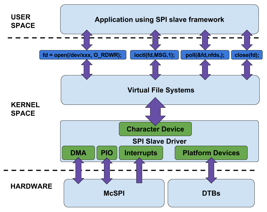
- Slave driver in Linux architecture
- Problems
- Development timeline
- Final raport
- Photos from tests
- AM335x and McSPI data sheets
- Books about Linux and LKM
- Building driver on x86 platform
- Prepare BB board
- Installing driver on BB platform
- First data transfer
- Testing and wiring
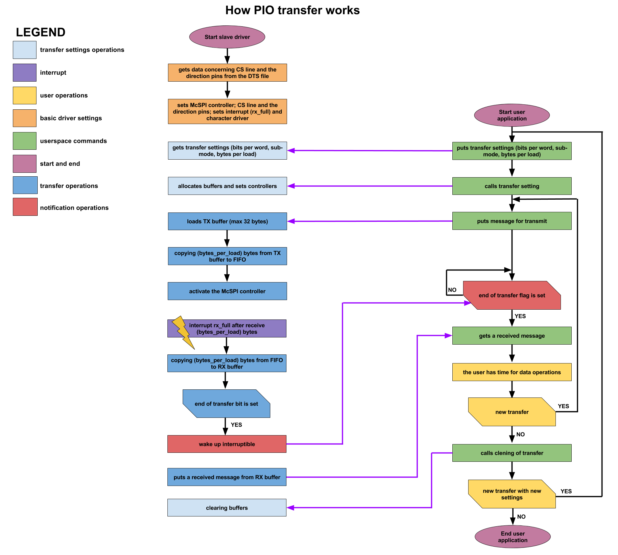
SPI slave driver implementation. The task is to create a driver controlling SPI hardware controller in slave mode, and to ensure optimal performance through the use of DMA and interrupt. Creating an easy to implement realization of SPI slave would definitely help the BeagleBone community members to write applications based on SPI much more easily. The first implementation of my protocol driver is going to example of a bidirectional data exchange. This application will provide the BeagleBone community with valuable experience and will be a good example of SPI slave. Hardware limitations make it impossible to perform any realization of the device using SPI slave. Sending away data to the master during one transaction is not possible. One transaction is enough to receive data by slave device. To receive and send back data, two transactions are needed. The data received from master device in a single transaction is transferred to the user after completing the transaction. The user's reply to received data is sent in the next transaction.
- Student: Patryk Mezydlo
- Mentors: Michael Welling, Andrew Bradford, Matt Porter
- Organization: BeagleBoard.org
- Code: https://github.com/pmezydlo/SPI_slave_driver_implementation
- Blog: https://github.com/pmezydlo/SPI_slave_driver_implementation/wiki
- Wiki: http://www.elinux.org/Pmezydlo
- GSoC site: https://summerofcode.withgoogle.com/projects/#5652864013697024
- Video presentation: https://www.youtube.com/watch?v=yBgMwMcvcKg
The framework in Linux should have 3 layers. In this way, there can be low level hardware interfaces to SPI hardware like McSPI in slave mode, a middle layer of common functions to call by protocol drivers, and then a top protocol driver layer which can be used to implement.
- The master device can begin the transaction at any time, even if the slave device isn't ready to receive data.
- The transfer can be of any length, as standard SPI does not specify the frame’s length. Theoretically, the master device can send so much data that the slave device would stop receiving it because of memory overflow.
- SPI interface is a rather fast interface (10s or 100s of MHz), so with too fast clock the system can’t keep up with generated interrupts. SPI slave controller will hammer the system with interrupts and the system might become unresponsive.
- Even if you manage to pass data to userspace during the transaction, user will have no time to return the response that will be transferred to the master in the same transaction.
- When transaction is short but often repeated, slave device has no time to set the DMA transfer.
- The register with the contents of the data to be sent must be loaded by DMA before the transaction (high state on cs line). There is no way to load a register of broadcasting prior to the transaction, because you do not know the address of the data to come back before the transaction.
- The slave device, after installing the driver and DTS, will be ready to receive the data. The user must set the SPI slave device before the master device.
- During the installation of the driver, the user must declare the maximum depth of data buffer. The length is the same for tx and rx. Transfer may be shorter, but not longer than the declared length.
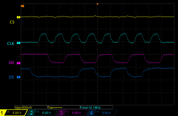
- The maximum speed of the slave mode specified in the documentation is 16Mhz as the maximum speed of SCLK line.
- Holding the response in memory and sending it in the next transaction solves the problem. The time between the transactions is greater than between the reception and transmission during a single transaction.
- Two-stage transactions allow to use DMA for loading and unloading mcspi buffer.
Each week I will devote a few hours to write the documentation.
-
Before the first week (before 24 May)
- create a GitHub repository ✔
- create eLinux page ✔
- create wiki page ✔
- prepare a few sd card with a Firmware Images ✔
- installation of necessary software ✔
- create .travis.yml script ✔
- create README.md ✔
- prepare video presentation ✔
- add license file ✔
- skeleton LKM ✔
- configure vim for kernel coding style ✔
-
Week 1(24 May - 31 May)
- create basic function: probe, remove, init exit ✔
- prepare test application(using spidev) ✔
- add more information about a driver works (describe main problems) ✔
- determinate McSPI base address (reading DTS device resources) ✔
- create device structure(keeps all the elements of the controller) ✔
- allocate memory for device ✔
- define McSPI register ✔
- function for reading and writing McSPI registers ✔
-
Week 2(31 May - 07 June)
- set driver in slave mode ✔
- set the majority of important registers, except for those related to DMA, interrupts and fifo ✔
- familiarizing myself with the basics of McSPI controller ✔
- reading and writing McSPI registers ✔
- synchronization (pm_runtime) ✔
- clean up all kernel coding style issues ✔
- resolve all warnings ✔
-
Week 3(07 June - 14 June)
- familiarizing myself and setting McSPI transmit register ✔
- first test (echo); send back data which the driver receives from master ✔
- setting interrupt (I had a few problems with this) ✔
- adding function which waits for register bit ✔
- second test (interrupt); generating interrupt after 4 bits and checking how subtracted words count ✔
-
Week 4(14 June - 21 June)
- transfer data from the FIFO to the driver buffer (for each word length) in both sides ✔
- finalized working on pio transfer ✔
- using tasklets for pio functions ✔
- a lot of tests (various lengths transfers and various length words(bits per word)) ✔
- beginning work on char driver as a framework for slave driver ✔
-
Week 5(21 June - 28 June)
- registration and removal of char driver for each platform device ✔
- adding functions: open, read, write, release, etc ✔
- adding device to device list ✔
- create application for user on slave device ✔
-
Week 6(28 June - 05 July)
- finalized work on char driver ✔
- improved prototype slave application and pio transfer ✔
- added ioctl ✔
- made thorough reconstruction of the driver ✔
-
Week 7(05 July - 12 July)✔
- finalized work on thorough reconstruction of the driver ✔
- first prototype test ✔
- finalized work on ioctl and poll ✔
- finalized work on prototype slave application and pio transfer ✔
- familiarizing myself with DMA ✔
- searched for bugs and repaired them ✔
- upgraded travis script ✔
- made a nice diagram ✔
-
Week 8(12 July - 17 July)
- configuring dma channel ✔
- interrupt for dma ✔
- create callback functions ✔
- finally work on DMA
- tests with DMA without API (printk log)
-
Week 9(19 July - 26 July)
- work on DMA ✔
- configuration of the DMA transfer (filling config structure) ✔
- added callback function ✔
- enable and disable DMA request ✔
- DMA channel request (old way) ✔
- clearing DMA source ✔
-
Week 10(26 July - 02 August)
- familiarizing myself with Buses ✔
- debugging dma ✔
- testing the driver in the 3.8.x version of the image (at the request of a colleague who is interested the driver) ✔
-
Week 11(02 August - 09 August)
- reated a new driver (spi-slave-core.ko) which manages bus ✔
- created a new device (spi-slave-dev.ko) which manages fs operations ✔
- added register and unregister spislave bus, devices and driver ✔
- created functions for the registration of other slaves (more generic framework) ✔
- matched device and driver after modalias ✔
- registered device which child node is located in DTS file ✔
- cleaned up code ✔
- prepared code for review by the linux maintainers (thanks Michael for this) ✔
-
Week 12(09 August - 20 August)
- clean up code✔
- latest tests ✔
- final raport ✔
- added headers with author and licence in the top of each file ✔
- corrected all inputs and outputs ✔
- BITMAP has been replaced with idr struct ✔
- mutexes and spinlocks ✔
- documentation, tutorials and examples ✔
The project’s initial version involved the creation of SPI driver in slave mode. The first implementation of realized framework was supposed to be SPI Flash Emulator. To ensure optimal performance, the driver was meant to use SPI controller, DMA and interrupt.
After contacting linux-spi and finding Marek Vašut, a developer who already had experience with SPI slave drivers, we had a constructive exchange of ideas. Marek introduced me to many critical elements. Michael noticed a limitation that made it impossible to create a fully generic slave driver. The project needed a thorough reconstruction.
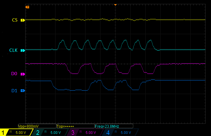
The project consists of three layers. The first and the lowest layer supports the SPI hardware controller. McSPI controller is located in BeagleBone Black, and the driver was developed exactly to this controller. The whole implementation is located in spi-mcspi-slave.c[1] file. The controller easily handles small transfers to 32 bytes with clock to 24 MHz. It supports a variety of word lengths, from 4 bits to 32 bits per word. DMA was supposed to provide support for longer transfer lengths; however, I was not able to develop it before the end of GSoC. DMA support will be added after GSoC.
The second layer is responsible for communication between the lowest layer and userspace. This layer consists of a core (bus) which connects the device and driver. It is a bus and a set of functions registering and managing other SPI slave devices. It was implemented in files spi-slave-core.c [2] and spi-slave-core.h [3]. Framework uses device tree overlay. On the basis of DTB, it matches the device to the driver. I have created two files dts for McSPI 0 slave.dts [4] and SPI1_slave.dts [5].
A simple user interface, allowing to carry out the transfer has been added in spi-slave-dev.c [6] and spi-slave-dev.h[7] files. For each installed device, the driver provides file in userspace (/dev/spislave0 and /dev/spislave1). The driver has the usual fs operations and a number of IOCTL functions (described in more detail in spi-slave-dev.h [7]), as well as POLL methods used to inform about the end of transaction.
I have added a simple spislave_app.c [8] application, which is using SPI slave framework. It is a good example on how to use SPI slave.
Documentation located on wiki page [9] and in the documentation directory [10] in repository describes the driver, clarifies and explains its limitations and shows the main problems because of which a fully generic spi driver in slave mode is difficult to obtain. It also provides information concerning work plan for each GSoC week. Moreover, it shows stage by stage how to compile, install and use the framework, as well as the way the master is connected to the slave on example of BeagleBoard Black.
- [1]spi-mcspi-slave.c
- [2]spi-slave-core.c
- [3]spi-slave-core.h
- [4]SPI0_slave.dts
- [5]SPI1_slave.dts
- [6]spi-slave-dev.c
- [7]api-slave-dev.h
- [8]slave_app.c
- [9]wiki
- [10]documentation/
- upstream process and interaction with maintainers
- how to create a variety of types of modules connected to the linux kernel
- handling devices mapped in memory
- creating a correct and visually aesthetic code compatible with the linux kernel coding style
- planning and describing a project
- how bus, device and driver work
- character device drivers and fs operations in practice
- methods for debugging and fault finding
- better git use
- and many more ;)
- AM335x ARM® Cortex™-A8 Microprocessors (MPUs) Technical Reference Manual: AM335x_Techincal_Reference_Manual
- Multichannel Serial Port Interface Technical Reference Manual: McSPI_Technical_Reference_Manual
- LINUX DEVICE DRIVERS, Third Edition, Jonathan Corbet, Alessandro Rubini, and Greg Kroah-Hartman pdf is here[1]
- Linux Kernel Development, Third Edition, Robert Love pdf is here[2]
[1]https://lwn.net/Kernel/LDD3/
[2]http://infoman.teikav.edu.gr/~stpapad/linux_kernel_development_3rd_edition.pdf
- Update your linux:
- Cross-compiler toolchain - To download the latest version of cross-compiler tool-chain:
- Cloning SPI slave repository:
- Check kernel version on your BB board (connect with your board):
- BBB clone kernel source:
- Cross compiling the kernel source:
- Cross compile SPI slave driver:
- Check the driver version:
$ sudo apt-get update -qq
$ sudo apt-get install bc
$ wget -c https://releases.linaro.org/components/toolchain/binaries/5.3-2016.02/arm-linux-gnueabihf/gcc-linaro-5.3-2016.02-x86_64_arm-linux-gnueabihf.tar.xz
$ tar xf gcc-linaro-5.3-2016.02-x86_64_arm-linux-gnueabihf.tar.xz
$ export CC=`pwd`/gcc-linaro-5.3-2016.02-x86_64_arm-linux-gnueabihf/bin/arm-linux-gnueabihf-
$ git clone git@github.com:pmezydlo/SPI_slave_driver_implementation.git
$ cd SPI_slave_driver_implementation/
$ git checkout
$ ssh root@192.168.7.2
$ uname -r
4.4.8-ti-r22
$ export SOURCE_BRANCH="4.4.8"
$ export SOURCE_VERSION="ti-r22"
$ export SOURCE_REPO="linux-stable-rcn-ee"
$ export SOURCE_LOCATION="https://github.com/RobertCNelson"
$ wget "$SOURCE_LOCATION/$SOURCE_REPO/archive/$SOURCE_BRANCH-$SOURCE_VERSION.tar.gz"
$ tar xf $SOURCE_BRANCH-$SOURCE_VERSION.tar.gz
$ export DST_KERNEL=$PWD/$SOURCE_REPO-$SOURCE_BRANCH-$SOURCE_VERSION
$ cd $DST_KERNEL
$ make -j3 mrproper ARCH=arm CROSS_COMPILE=$(CC) LOCALVERSION=-$SOURCE_VERSION
$ wget -c "http://rcn-ee.net/deb/jessie-armhf/v$SOURCE_BRANCH-$SOURCE_VERSION/defconfig" -O .config
$ make -j3 modules ARCH=arm CROSS_COMPILE=$(CC) LOCALVERSION=-$SOURCE_VERSION 2>&1
make KDIR=$DST_KERNEL ARCH=arm CROSS_COMPILE=$(CC) LOCALVERSION=-$SOURCE_VERSION
$ modinfo driver/spi-mcspi-slave.ko
filename: /home/pmezydlo/BeagleBoard_work/SPI_slave_driver_implementation/driver/spi-mcspi-slave.ko
version: 1.0
description: SPI slave for McSPI controller.
author: Patryk Mezydlo,
license: GPL v2
srcversion: 469EA334B14612EBD6F0463
alias: of:N*T*Cti,omap4-mcspi*
depends:
vermagic: 4.4.8-ti-r22 SMP mod_unload modversions ARMv7 thumb2 p2v8
- Mount the FAT partition:
- Edit the uEnv.txt on the mounted partition:
- To disable the HDMI Cape, change the contents of uEnv.txt to:
- Save the file:
- Unmount the partition:
- Reboot the board:
- Wait about 10 seconds and reconnect to the BeagleBone Black through SSH. To see what capes are enabled:
$ mount /dev/mmcblk0p1 /mnt/card
$ nano /mnt/card/uEnv.txt
$ optargs=quiet capemgr.disable_partno=BB-BONELT-HDMI,BB-BONELT-HDMIN
Ctrl-X, Y
$ umount /mnt/card
$ shutdown -r now
$ cat /sys/devices/bone_capemgr.*/slots
- Create a file:
- Edit the spi_omap2_mcspi.conf:
- Save the file:
- Reboot the board:
$ nano /etc/modprobe.d/spi_omap2_mcspi.conf
blacklist spi_omap2_mcspi
Ctrl-X, Y
$ shutdown -r now
- Installing the DTS compiler:
- Compiling the SPI slave dts file:
$ wget -c https://raw.githubusercontent.com/RobertCNelson/tools/master/pkgs/dtc.sh
$ chmod +x dtc.sh
$ ./dtc.sh
$ cd DTS/
dtc -O dtb -o SPI0_slave-00A0.dtbo -b 0 -@ SPI0_slave.dts
- Upload using SCP:
$ scp driver/spi-mcspi-slave.ko root@192.168.137.2:/root
$ scp slave_app/slave_app root@192.168.137.2:/root
$ scp DTS/SPI0_slave-00A0.dtbo root@192.168.137.2:/lib/firmware
- Make an entry:
- Checking:
echo SPI0_slave>/sys/devices/platform/bone_capemgr/slots
$ cat /sys/devices/platform/bone_capemgr/slots
0: PF---- -1
1: PF---- -1
2: PF---- -1
3: PF---- -1
5: P-O-L- 0 Override Board Name,00A0,Override Manuf,SPI0_slave
- Command insmod:
- Checking:
insmod spi-mcspi-slave.ko
$ lsmod
Module Size Used by
spi_mcspi_slave 10781 0
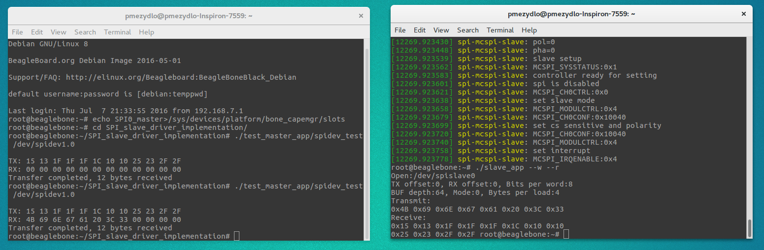
- Run SPI slave application:
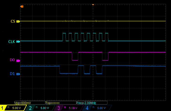
- Application and driver waiting for the data, connect the master and make your first transfer!!!
./slave_app --w --r
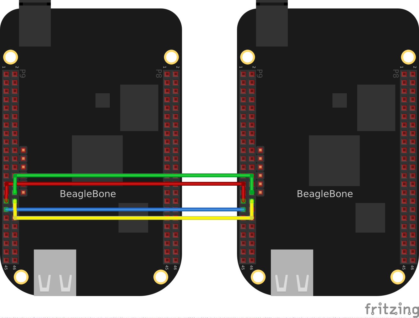
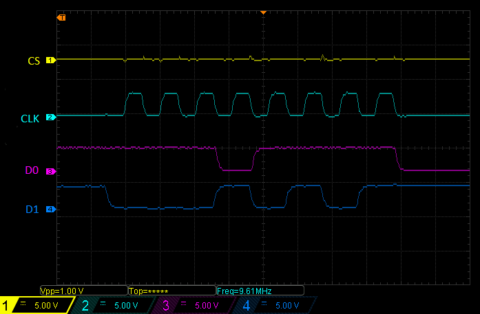
One AM335x processor contains two McSPI controllers, what allows to use one controller as slave and the other as master. This allows to carry out tests on one board.
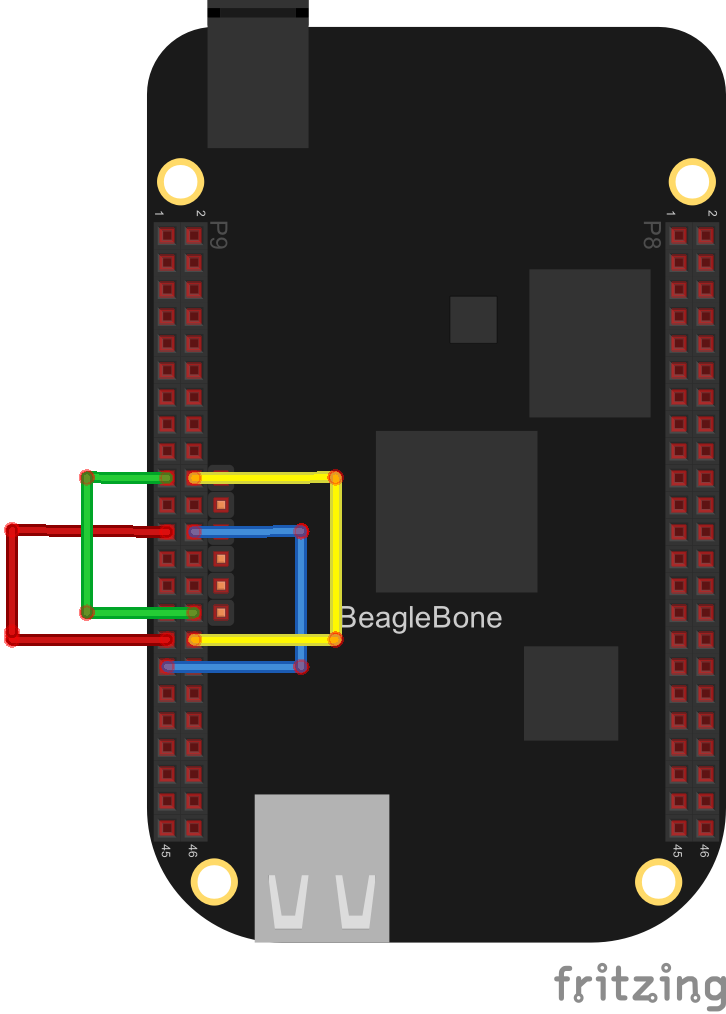
The second option is to use two boards where one works as master and the other as slave.