This project shows how to connect a sound sensor (analogic) and how to display its output in a LED bar display using LinkIt 7697.

If you want to use the LinkIt 7697 with the Arduino IDE, follow this tutorial. As a summary:
- Go to File -> Preferences and in the Additional Boards Manager URLs, type
http://download.labs.mediatek.com/package_mtk_linkit_7697_index.json
- Then go to Tools -> Boards -> Board Manager... and in the search box look for LinkIt. Install the additional libraries.

- Finally install the USB driver (CP210x) from here, selecting the correct OS configuration.

In order to correctly connect the board and the sensors, the code has to be analyzed first.
In order to use the LED Bar, we need to import the Grove_LED_Bar library and initialize the Grove_LED_Bar object as follows.
#include <Grove_LED_Bar.h>

Grove_LED_Bar bar(9, 8, 0);	// Clock pin, Data pin, Orientation. Modify for your input pin (in our case, pin 8 in the LinkIt 7697).
Note that the LED bar has only 3 important pins: 3.3V, Gnd and its input. In this case, the input is on pin 8.
For starting it, just add the begin command to setup.
void setup()
{
	Serial.begin(9600);	//We print to serial monitor
	bar.begin();		//Initialize the LED bar.
}
Finally, the LED bar has 10 LEDs, so it can display any binary number between 0 and 2^10-1=1023. In order to do so, in the loop section use the following code
void loop()
{
	//LED use binary from 0 to 1023 = 2^10-1. There are 10 slots in the LED bar.

	...

	int i=153;

	bar.setBits(i);		//Turns on the LED bar and sets the number.
	Serial.println(i);	//Prints the value in serial monitor.

	...
}
where the function setBits(i) has an input from 0 to 1023. Please be aware that if a greater or lower number is given, an overflow or underflow will happen and a different number will be displayed.
The sound sensor used in this project was a standard analog sound sensor.

In order to read its inputs, we need to define the analogic pin that will provide the board with the sensors data.
const int pinAdc = A0;
and we need to read its content inside the loop cycle as
void loop()
{
	...

	long value = analogRead(pinAdc);

	Serial.println(value);	//Prints the value in serial monitor.

	delay(100);	//Sets up a delay.

	...
}
Because in our code we find the lines
const int pinAdc = A0;
Grove_LED_Bar bar(9, 8, 0);	// Clock pin, Data pin, Orientation. Modify for your input pin (in our case, pin 8 in the LinkIt 7697).
We then need to update the connections accordingly:
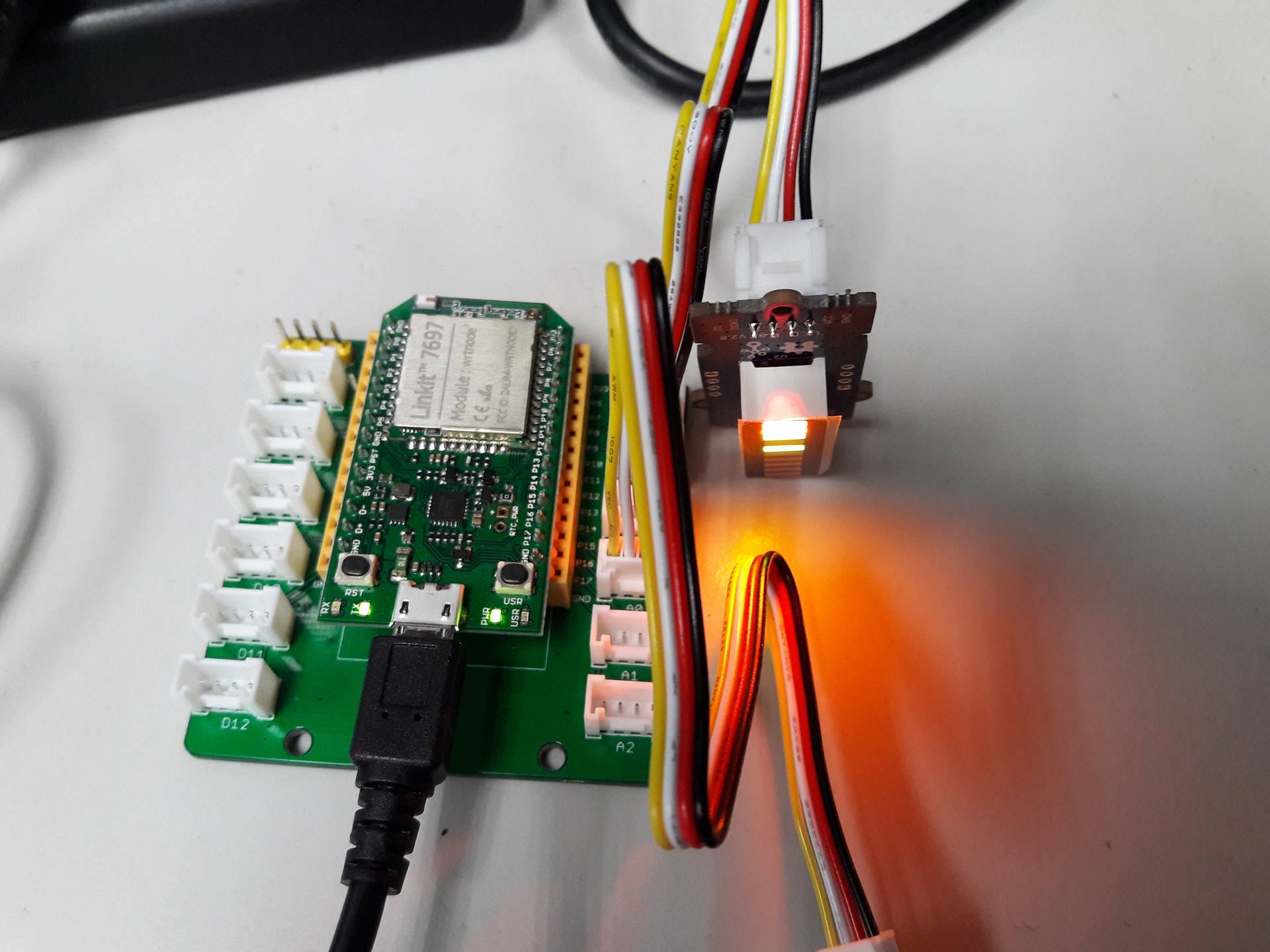
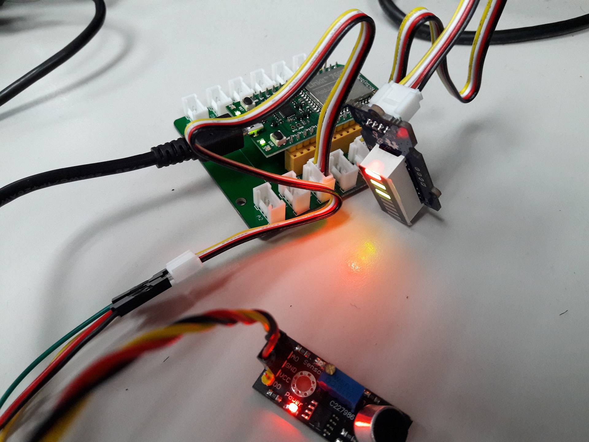
- Connect the LED bar to the IC2 port.
- Connect the sound sensor to the A0 port.

Please beware that in both ports, the GND and 3.3V pins match with the GND and 3.3V pins in both the LED bar and the sensor.
This project can be modified to use any other analogic sensor, such as a light sensor. Just connect it to the A0 port.
A demo of the LED bar displaying different values depending on the detected sound intensity can be seen below.