Hardware


STL file for Raspberry Pi 2/3/4 with LCD and rotary encoder
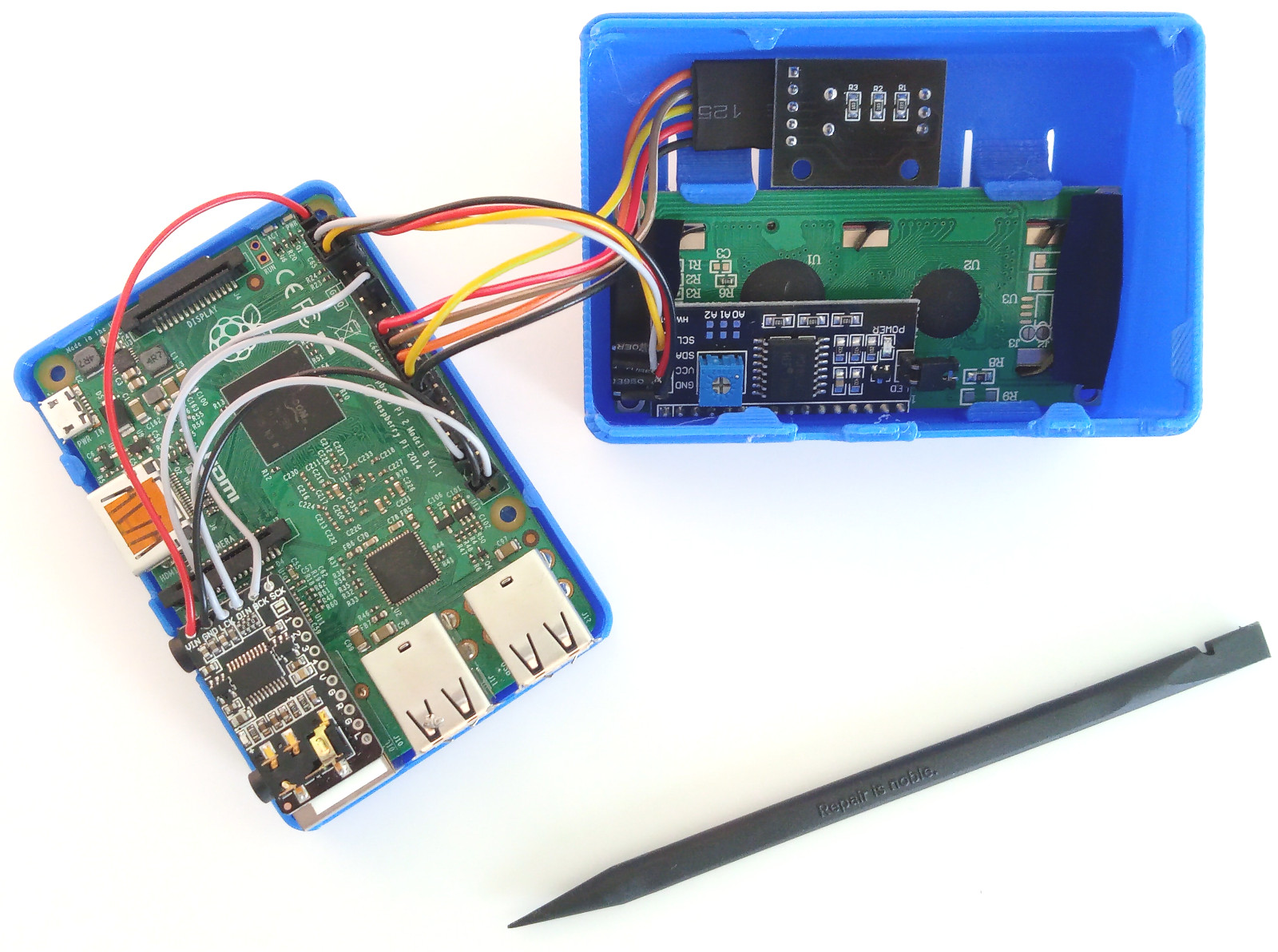
Please note: MiniDexed can be used without any hardware attached to the Raspberry Pi GPIOs. All hardware is optional and there are a number of different control schemes but this one is a good starting point:
- 16x2 character LCD
- Rotary encoder
- DAC for audio output
- Optional link to a 3V3 compatible MIDI module
Schematic:

Wiring diagram:

GPIO Pin Summary:
| GPIO | Pin | Description |
|---|---|---|
| 2 | 3 | I2C SDA (Optional) |
| 3 | 5 | I2C SCL (Optional) |
| 4 | 7 | LCD RS |
| 9 | 21 | Encoder DT |
| 10 | 19 | Encoder CLK |
| 11 | 23 | Encoder Switch |
| 14 | 8 | TXD - MIDI OUT |
| 15 | 10 | RXD - MIDI IN |
| 17 | 11 | LCD E |
| 18 | 12 | DAC I2S BCK |
| 19 | 35 | DAC I2S LCK |
| 21 | 40 | DAC I2S DIN |
| 22 | 15 | LCD D4 |
| 23 | 16 | LCD D5 |
| 24 | 18 | LCD D6 |
| 25 | 22 | LCD D7 |
Thanks @diyelectromusic (Details)
LCD1602 display or similar. Midas MCOB21605C1V-EWP OLED is also known to work. Both "raw" displays and displays with an i2c "backpack" are supported by the software. So you can get a display with or without an i2c "backpack" board. An an i2c "backpack" board greatly simplifies the setup because fewer physical connections need to be made.
An an i2c "backpack" board comes with a built-in potentiometer to adjust contrast. If you are not using An an i2c "backpack" board, you can use a 10k potentiometer between the contrast pin (V0) and GND. The contrast varies with a changing environment temperature. If you don't have a 10k potentiometer at hand, a 2.2k resistor may also do the job, but you may have to experiment with the exact value. If you have a display with an i2c "backpack" PCB, there is already a contrast potentiometer installed.
WARNING: Simpler backpacks are designed to be powered by 5V and include pull-up resistors on the I2C bus to 5V too. If you have one of these you will need a 3V3 to 5V level shifter to avoid pulling up the Pi's I2C GPIO pins to 5V! Alternatively it may be possible to remove (desolder) the built-in pull-ups to 5V and add new ones to 3V3. If you're not sure what kind you have, power the LCD from 5V and GND only and measure the voltage on the I2C pins to see if it is 5V or 3V3.
Non-backpack LCDs, whilst still powered by 5V, are only connected to Pi GPIO outputs, so driving them at 3V3 from the Pi is fine.
Pinout with backpack assuming no level shifting is required (thanks @Banana71):

There is also support for SSD1306 128x32 and 128x64 i2c OLEDs. These displays can be used via i2c. Currently there is only text mode supported, but any work that would allow us to show graphical representations of the algorithms would be highly welcome!
WARNING: Once again some of these displays assume 5V power and some 3V3, and some can be powered from 5V and still be fine with a 3V3 I2C bus. As a general rule, the 128x32 (shown left) tend to include a level shifter, meaning they can be powered from 5V but only pull-up I2C to 3V. The 128x64 (shown middle and right) often don't so the I2C bus may be pulled-up to VCC. The level shifter can usually be spotted on the board if you examine it. The photo on the right shows a 128x64 board that does include the level shifter (marked "U2"), but once again, measure the voltage on the I2C connections prior to connecting to your Pi!


There is some support for ST7789 displays. This is not enabled by default and will need to be configured in minidexed.ini (details here).
Given the wide range of ST7789 displays available, there is no guarantee that any specific display will be supported, and some bespoke configuration is almost certainly required. For these reasons, the use of ST7789 displays is considered an advanced option for those wishing (and willing) to experiment.
KY-040 rotary encoder or similar.
To improve precision, solder in 2 10nf capacitors: CLK to ground and DT to ground. Some breakout boards may even have empty pads for 0603 size capacitors to be soldered in.

Sample picture: KY-040 with two 10nF capacitors
Buttons can be attached to GPIO pins which will be configured for "PULLUP" mode. This means that any buttons only need to momentarily connect the appropriate GPIO pin to GND to activate the button.
Button configuration options are available for any the following:
- Menu Prev/Next/Select
- Back and Home
- Program change (up/down)
- TG select (up/down)
All buttons can optionally also be triggered over MIDI using CC or Note messages.
This provides the following options for user interface controls:
- Display with switched rotary encoder.
- Display with rotary encoder and select/back/home.
- Display with prev/next/select/back/home.
- Program up/down and TG up/down (for a simple headless system that just requires voice selection).
- Display with MIDI controls for prev/next/select/back/home.
- MIDI controls for headless operation for program and TG up/down.
For more details refer to the explanations of the appropriate configuration settings in minidexed.ini and the MIDI implementation.
The headphone jack on the Raspberry Pi is known to produce very low quality, noisy sound. Hence it is suitable for functional testing at best. For everything else, you need to either use an i2c DAC or HDMI audio.
PCM5102A and PCM5122 based DACs are supported.
The GY PCM5102 DAC module (schematic) (also its variant HW-823) and the CJMCU 5102 DAC module seem to be reasonably priced I2C DAC modules.
Once again for any DIY solution, check the IO voltages are compatible with the Pi. In the case of the GY-PCM5102 modules, they include an on-board power stabiliser to ensure 3V3 operation (and interface) when powered by 5V.
HifiBerry DACs seem to use the same chips but are much higher priced.
The ES9023 based TeraDak.com board has been reported to work.
UDA1334A based DACs also work.
MAX98357 based Mono DACs with built-in amplifiers also work (but according to this volume is a bit low).
User reported working and non-working hardware is being discussed here.
Please note: We don't know whether MiniDexed can work with other DACs. DACs that only use I2S are more likely to work than DACs that use I2S and I2C, which may require an I2C initialization sequence that is different for each DAC model. If you have your I2S+I2C DAC working in Linux, you can make a dump of its registers as a starting point... and then get it ported to the (Circle)[https://github.com/rsta2/circle/] environment which MiniDexed is based on.
As an inexpensive, solder-free alternative you can use a HDMI to VGA adapter with audio out.

For it to work, you need to simulate a VGA screen being attached by using a resistor, because otherwise the sound will be silent.

Tested on a Raspberry Pi 2 and on a Raspberry Pi Zero.
By default, MiniDexed will act as a USB MIDI host and accept (Audio/MIDIStreaming) class compliant USB MIDI devices connected to it (e.g., MIDI controllers such as keyboards). If your device isn't recognized, then there are some additional USB options that can be specified in the cmdline.txt file that might help compatibility. In USB host mode (which is the default), MiniDexed cannot be connected to a host computer over USB (e.g., to send MIDI data from the host computer to MiniDexed). But some Raspberry Pi models can be configured to use USB Gadget Mode instead of USB Host mode, which allows MiniDexed to be used as a USB MIDI device instead - i.e. plugged into (and powered from) another USB host such as a PC running a DAW. For details of how to use MiniDexed in this way, see "USB Gadget Mode" below.
- Note: If you find selecting voices "hangs" with a USB MIDI device plugged in and see "xhciep: Transfer timed out" on the console whenever you change voice or performance then it might be related to the
MIDIAutoVoiceDumpOnPCoption (details here). If your USB MIDI device isn't expecting to receive data, having this option set could mean MiniDexed is spamming it with SysEx voice data, which it probably won't like!
Alternatively it is possible to build an adaptor that can act as a USB device and generate MIDI to send to MiniDexed. Possible methods to achieve this are:
- Build an adapter using a Raspberry Pi Pico and the firmware from https://github.com/rsta2/pico/tree/main/midi_adapter, midi_adapter.uf2.zip. This adapter acts as a USB-MIDI device on the computer, and feeds the MIDI data into the serial input (RXD) on the MiniDexed device.
- This is a CircuitPython based solution for use with any supported boards that can act as USB devices.
- This is a USB MIDI Device "co-processor" using a Seeed XIAO SAMD that can be plugged directly into a Raspberry Pi.
- It is also possible to use an Arduino, but that may be more complex compared to any of the above (more here).
The following Raspberry Pi boards can act as a USB device using "USB Gadget Mode":
- Raspberry Pi 1 A and A+
- Raspberry Pi 3 A+
- Raspberry Pi 4
- Raspberry Pi Zero, Zero W and Zero 2W
As a USB Gadget (device) the Pi can be plugged into a USB host and "just work" as a USB MIDI device with no other connections required other than sound output. MiniDexed provides a class compliant USB MIDI end point, meaning it should "just work" with any system that supports class compliant USB MIDI. It does not allow USB audio or access to the SD card.
In USB Gadget mode the Pi will obtain its power from the USB host it is plugged into and it MUST NOT be powered independently.
Also, the Pi cannot be used as a USB gadget (device) and USB host at the same time so it will not support other USB peripherals being plugged in whilst in USB Gadget mode even if the onboard USB ports are not otherwise in use.
To run a Raspberry Pi as a USB device requires the following connections to connect to a USB host (such as a PC):
- Pi A, A+ or 3A+ - use a USB A to USB A lead. Do NOT use the micro-USB socket for power.
- Pi 4B - use the USB C socket with a USB C to USB C or USB C to USB A lead. Do NOT use the USB A sockets.
- Pi Zero, Zero W, Zero 2 - use a micro USB to USB A lead or "OTG adaptor" in the "USB" micro USB socket. Do NOT use the micro USB "PWR IN" socket.
Important: As stated above, the Pi cannot be powered as a USB device and via independent power at the same time. However it is possible that the USB device link might not supply enough power for MiniDexed to run with additional peripherals. Some users have found inventive ways to solve this problem - there is some discussion here: https://forums.raspberrypi.com/viewtopic.php?t=352564 - but this is NOT recommended for use with MiniDexed unless you already know what you are doing.
USB Gadget (device) mode can be enabled at boot time by setting USBGadget=1 in MiniDexed.ini.
Hardware Control of USB Mode
It is also possible to configure a USBGadgetPin when USBGadget=1 to enable hardware control over the USB mode. If USBGadgetPin is configured to a GPIO number and that corresponding GPIO pin is connected to GND on boot then USB Gadget (device) mode is enabled. If the configured USBGadgetPin is left unconnected (so pulled HIGH) then USB host mode is enabled. By default, USBGadgetPin=0 so that the mode is set by USBGadget only.
The default is USBGadget=0, i.e. run in "normal" USB host mode. MiniDexed has its own USB vendor and device ID of 0x1209 and 0cF043. This cannot be changed without a rebuild from source.
If USB Gadget mode is enabled on a Pi that doesn't support it, MiniDexed will halt on power up with messages displayed on the HDMI console.
Be sure to use the correct USB connection for the chosen USB mode otherwise you could damage your Pi.
Thanks to Raspberry Pi builtin serial port, MiniDexed will happily accept Classic MIDI messages. There are a number of options for this. The following have been shown to work:
- Clumsy MIDI Interface
- MiniDexed Raspberry Pi IO Board
- Add other MIDI interface modules here...
An alternative DIY MIDI IN circuit can be constructed using an optocoupler, diode and resistors. This is the circuit recommended by @diyelectromusic for use with 3V3 logic levels:

Notes:
- This shows 5-pin DIN and TRS sockets, but only one is required. The TRS is wired for "Type A" (as per the MIDI spec) operation.
- A 1N914 is shown, but really any small signal diode should be fine - e.g. 1N4148.
- A H11L1 Schmitt Trigger Output Optocoupler is recommended (there are other similarly labelled chips that won't work - more here).
There is a discussion relating to DIY MIDI OUT for 3V3 systems here.
Warning: DO NOT use any of the 5V logic level circuits you'll find on the Internet (e.g. those using the 6N138 at 5V designed for use with an Arduino). Feeding a 5V RX level from an optocoupler into the Raspberry Pi's RX pin will damage the Pi.
Below is the original circuit described for use with MiniDexed that was apparently successfully tested on a Raspberry Pi 1B+ but that has had reports of possibly not being optimal. Please see this discussion.
