External ADC
Here is a list of the most frequent analog to digital converters that can be used as I2S source by the framework. When you have a new device I recommend to start with the streams-i2s-serial sketch so that you can verify the data that you receive. A typical 2 channel int16_t audio signal might look as this:
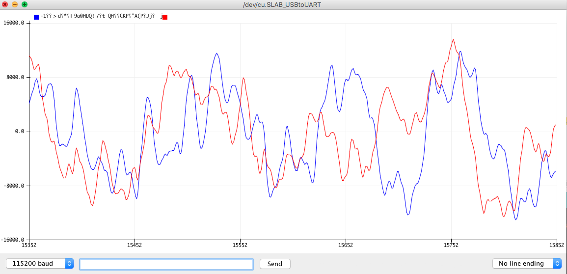
Some modules only provide data on one channel and sometimes the other channel contains noise! So there is no point in trying any other sketch before you have a clear understanding of your module!
The easiest way to analyze the data is to record a sine tone (e.g. with the help of an online tonegenerator) and then display the result in Arduino Serial Plotter: You are supposed to see a sine wave there as well!
The framework uses the following default I2S pins for the ESP32:
- PIN_I2S_BCK = 14
- PIN_I2S_WS = 15
- PIN_I2S_DATA_IN = 32
Please double check the actual settings in AudioConfig.h for your Processor. You can also change the pins in your sketch:
  auto config = i2sStream.defaultConfig(RX_MODE);
  config.pin_bck = 14;
  config.pin_ws = 15;
  config.pin_data = 22;
  i2sStream.begin(config);
Some processors (the ESP32) support input and output at the same time. For this case you can use
  auto config = i2sStream.defaultConfig(RXTX_MODE);
  config.pin_bck = 14;
  config.pin_ws = 15;
  config.pin_data = 22; // output
  config.pin_data_in = 23; // input
  i2sStream.begin(config);
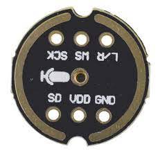
The INMP441 is a high-performance, low power, digital-output, omnidirectional MEMS microphone with a bottom port. The complete INMP441 solution consists of a MEMS sensor, signal conditioning, an analog-to-digital converter, anti-aliasing filters, power management, and an industry-standard 24-bit I²S interface. The I²S interface allows the INMP441 to connect directly to digital processors, such as DSPs and microcontrollers, without the need for an audio codec in the system.
| INMP441 | ESP32 |
|---|---|
| VDD | 3.3 |
| GND | GND |
| SD | IN (GPIO32) |
| L/R | GND |
| WS | WS (GPIO15) |
| SCK | BCK (GPIO14) |
- SCK: Serial data clock for I²S interface
- WS: Select serial data words for the I²S interface
- L/R: Left / right channel selection When set to low, the microphone emits signals on one channel of the I²S frame. When the high level is set, the microphone will send signals on the other channel.
- SD: Serial data output of the I²S interface
- VCC: input power 1.8V to 3.3V
- GND: Power groundHigh
I2SStream i2sStream;
auto cfg = i2sStream.defaultConfig(RX_MODE);
cfg.i2s_format = I2S_STD_FORMAT; // optional because default setting
cfg.bits_per_sample = 32;
cfg.channels = 2; // optional because default setting
cfg.sample_rate = 44100;
cfg.is_master = true; // optional because default setting
i2sStream.begin(cfg);
The sample_rate is just a proposal and you can adjust it to your needs. Please note that clean data is provided only on one channel as int32_t and that cfg.bits_per_sample = 16 might most likely just produce noise on one channel that you might have to filter out e.g. with a ConverterFillLeftAndRight!
The ESP32 supports PDM via the I2S API. So we can use this Microphone as well. For all other processors you need to install a PDM library.
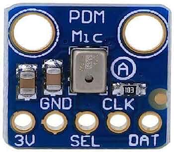
- SEL: Select Left or Right
- CLK: Clock Pin
- DAT: Data Pin
| MP34DT01 | ESP32 |
|---|---|
| 3V | 3V |
| GND | GND |
| SEL | GND (GND or 3.3V) |
| CLK | WS (GPIO15) |
| DAT | IN (GPIO32) |
| - | BCK (GPIO14) |
I2SStream i2sStream;
auto cfg = i2sStream.defaultConfig(RX_MODE);
cfg.bits_per_sample = 16;
cfg.channels = 1;
cfg.sample_rate = 44100;
cfg.signal_type = PDM;
cfg.channel_format = I2S_CHANNEL_FMT_ALL_RIGHT;  // or left ?
cfg.use_apll = false;
cfg.auto_clear = false;
//cfg.pin_bck = I2S_PIN_NO_CHANGE; // not used
//cfg.is_master = true; // optional because default setting
i2sStream.begin(cfg);
Please note that the WS is connected to the CLK of the microphone! You can select if you receive only data on the left or right by setting SEL to high or low.
Usually you do not need any master clock, but unfortunately we need to feed this module with a master clock signal from the ESP32, if the ESP32 is acting as master.
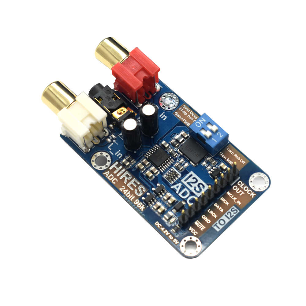
| i2s-ADC | ESP32 |
|---|---|
| MCCLK_IN | RX_0 (GPIO3) |
| BICK | BCK (GPIO14) |
| DATA | IN (GPIO32) |
| RLCLK | WS (GPIO15) |
| GND | GND |
| MUTE | - |
| VCC | VIN 5V |
I2SStream i2sStream;
auto cfg = i2sStream.defaultConfig(RX_MODE);
cfg.i2s_format = I2S_STD_FORMAT; // or try with I2S_LSB_FORMAT
cfg.bits_per_sample = 32;
cfg.channels = 2; // optional because default setting
cfg.sample_rate = 44100;
cfg.is_master = true; // optional because default setting
// this module needs a master clock if the ESP32 is master
cfg.use_apll = false;
cfg.pin_mck = 3;
i2sStream.begin(cfg);
The sample_rate is just a proposal and you can adjust it to your needs. Please note that the data is provided on both channels as int32_t!