Tutorial
Building an AHRS using the SparkFun "9DOF Razor IMU" or "9DOF Sensor Stick"
Razor AHRS v1.4.2 — See the Changelog
Overview
- Intro
- Setting up the hardware
- Setting up the software
- Testing the tracker
- Sensor calibration
- Using the tracker
- Writing your own code to read from the tracker
- Mathematical background and firmware internals
- Troubleshooting
- Donation
This tutorial describes how to put together an Attitude and Heading Reference System (AHRS) which does not cost much (around 140$/120€) and works very well. It can be used in projects requiring real-time 3D orientation tracking such as
- Robots
- UAVs and autonomous vehicles
- Image stabilization systems
- Head-tracking, e.g. for binaural audio applications (The SoundScapeRenderer - a spatial audio reproduction tool - has Razor AHRS support built in. My Android Mobile Dynamic Binaural Synthesis project is using the tracker as well.)
Watch a demo video:
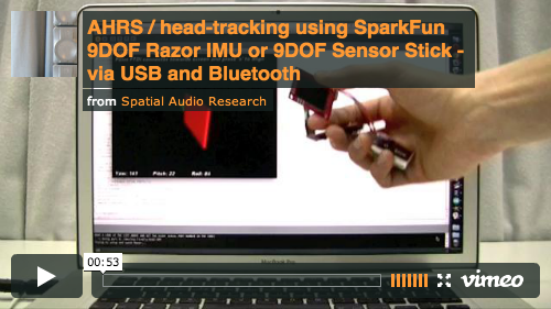
The tutorial will show you how to build a wired version of the tracker (connected via USB), as well as a wireless version (using Bluetooth).
Of course it’s also possible to integrate it into your hardware projects directly by connecting to the RX/TX pins, e.g. using an Arduino board.
This Razor AHRS Firmware is based on an update of the older AHRS code for a previous version of the Razor board. That code didn’t get updated for newer versions of the board, was a little messy (no offense!) and was also lacking some features I wanted to have and found necessary - e.g. sensor calibration to improve precision - so I extended and partly rewrote it and decided to make it public.
Improvements over the updated AHRS code currently provided by SparkFun include:
- Much better performance due to sensor calibration
- Binary and text output modes
- Serial command interface
- Easy to understand, setup and extend
- Outputs correct angles right after start-up, instead of converging slowly
- Processing test-sketch available
- C++ library available for Mac OSX, Unix and Linux
- Android library available for Android 2.0 and newer
Feedback and contributions welcome: https://github.com/ptrbrtz/razor-9dof-ahrs

NOTE: This section about setting up the hardware was written for the 9DOF Razor IMU. If you’re using the 9DOF Sensor Stick you’ll have to figure out how to set it up yourself, though most things mentioned here can be adapted.
The big difference is that the Sensor Stick does not come with a microcontroller on board, so most people will end up connecting it to an Arduino, which will run the firmware and do all the communication. With this older port by Luke Petre it can also be run using mbed microcontrollers.
Currently the firmware supports the 9 Degrees of Freedom - Razor IMU boards with SparkFun product numbers SEN-10125 and SEN-10736 and 9 Degrees of Freedom - Sensor Stick boards with SparkFun product numbers [SEN-10183] (http://www.sparkfun.com/products/10183), SEN-10321 and SEN-10724.
For the wired solution (via USB) using the 9DOF Razor IMU you need:
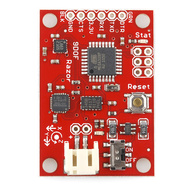
- The 9 Degrees of Freedom - Razor IMU board (or compatible).
- The FTDI Basic Breakout - 3.3V board (or compatible) and a
USB mini-B cable to connect it to your computer.
- Alternatively using an FTDI Cable instead of the breakout board should also work, but be sure to get the 3.3V version.
For the wireless solution (using Bluetooth) you additionally need:
- A Bluetooth Modem. I used the Bluetooth Mate Gold which is quite expensive. Cheaper ones should work too as long as they support the Serial Port Profile (SPP). Almost all modules support SPP.
- A Lithium Polymer (LiPo or LiPoly) battery to power the whole thing. The battery should be single-cell and thus have 3.7V nominal voltage. Pick a capacity based on your needs. I'm using 400mAh, which is still pretty small and can power the Razor and the Bluetooth Mate Gold for about 6 hours. Make sure the battery has an integrated low-voltage cutoff circuit to prevent deep discharge. LiPo batteries die if they get discharged too low.
- A LiPo charger. I used the SparkFun USB LiPoly Charger - Single Cell which is cool because it also uses a USB mini-B plug and you can charge without having to replug the battery. It is also possible to charge and draw from the battery at the same time.
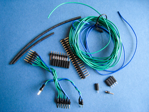
You will also need soldering equipment and some pin headers and jumper wires to connect the parts (see next section). You could also use some stranded wire and heat shrink to make your own custom-lenght jumper wires:
All the links posted point to the US SparkFun site which is a greatplace to look for parts, but in case you don’t live in the States (like me), you might want to find a SparkFun distributor in your country. In Germany Watterott is a good alternative.
-
Assembling the wired tracker using the 9DOF Razor IMU is pretty simple:
Depending on your jumper wire having male or female connectors, solder some pin headers to the FTDI connectors on the Razor board like this:

Now connect the FTDI Breakout and the Razor. The I/O header layout of the FTDI Breakout matches the header layout of the Razor (but connect GND to GND of course).
 FTDI BREAKOUT <--> RAZOR
 GND           <--> GND
 CTS           <--> CTS
 3.3V          <--> 3.3V
 TXO           <--> RXI
 RXI           <--> TXO
 DTR           <--> DTR
(The FTDI Breakout says 5V, but it’s actually outputting 3.3V - I used the jumper on the backside to change it)
-
Assembling the wireless version is also pretty simple:
-
If the plug of your LiPo battery does not connect with the connector on your LiPo charger you could solder some pin headers to the battery and the charger like this:

-
Add pin headers to power the Razor like this:
-
If your Bluetooth Modem does not have pin headers already, add them:

-
Use some more jumper wires and connect everything. When connecting take care about +/- polarities. The I/O header layout of the Bluetooth Mate also matches the header layout of the Razor (connect GND to GND of course), so you can use the same jumper wire you used to connect to the FTDI Breakout. If you use a different Bluetooth modem, you might have to reorder the wiring.
  BLUETOOTH MATE <--> RAZOR
  GND            <--> GND
  CTS-I          <--> CTS
  VCC            <--> 3.3V
  TX-O           <--> RXI
  RX-I           <--> TXO
  RTS-O          <--> DTR
-
NOTE: Do not solder any wire to the boards directly. Even when using the tracker with Bluetooth, you still need the wired USB setup to program it. So you have to be able to plug/unplug connections between the boards.
-
WARNING: When you go from Bluetooth setup to the wired USB setup, make sure you disconnect the battery as well and not just replace the modem with the FTDI connector. You would connect the battery to your computer, which is not a good idea.
-
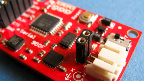
By using the little
ON/OFFswitch on the board you can completely turn off the tracker to save battery. Charging the battery is always possible, no matter if the board is switchedONorOFF.
-
- Clone or download and unzip the latest Razor AHRS Firmware from GitHub.
- Download and install the Arduino Software. We will use it to upload the firmware and calibrate the sensors. Any Arduino versions 1.x should work fine, tested with version 1.0.5 and 1.5.8.
- Even if you want to use Bluetooth later on, setup the tracker using USB for now (see How to put it together) and connect it to your computer. Uploading does not work via Bluetooth.
- From your downloaded Razor AHRS Firmware package open the file
Arduino/Razor_AHRS/Razor_AHRS.inousing Arduino. - In Arduino:
- Have a look at the top of the
Razor_AHRS.inofile, it contains useful information about the firmware. - Also there is a section labeled
"USER SETUP AREA"where you can set some firmware defaults.- You have to select the hardware you are using under
"HARDWARE OPTIONS"!
- You have to select the hardware you are using under
- Go to
"Tools"→"Board"and select the board you are using. If you have a 9DOF Razor IMU, select"Arduino Pro or Pro Mini (3.3v, 8mhz) w/ATmega328". Note: in Aduino 1.5+, the board menu doesn't allow selecting the voltage/frequency; go to the Processor menu after selecting "Arduino Pro or Pro Mini" and select "ATMega 328 (3.3V, 8Mhz)" - Go to
"Tools"→"Serial Port"and select the port used with the Razor. On Mac OSX this is most likely the first in the list. On Windows/Linux that might be different. - Go to
"File"and hit"Upload to I/O Board". After a short while at the bottom of the Arduino code window it should say"Done uploading".
- Have a look at the top of the
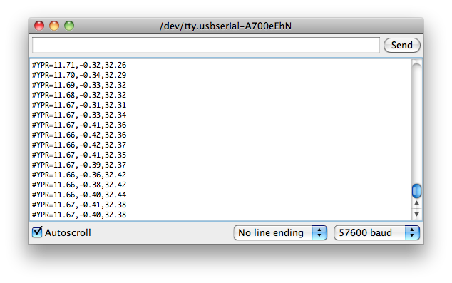
To test by staring at numbers, bring up the Serial Monitor of Arduino under "Tools" → "Serial Monitor". Set it to 57600 baud and you should get some output like this:
Go ahead and try the commands listed in Razor_AHRS.ino by typing them into the edit box at the top of the Serial Monitor. For example you can switch to binary output by sending #ob and should see something like this:

You can also use the Processing test sketch to test the tracker:
- Download and install Processing. We will use it to compile and run the test program. Any Processing versions 2.x should work fine, tested with version 2.0.3.
- NOTE: There seems to be a bug with the serial library in Processing versions 1.5 and 1.5.1: "WARNING: RXTX Version mismatch …". (So use a newer version 2.x or get the older 1.2.1, which also works and is still available here).
- From your downloaded Razor AHRS Firmware open the file
Processing/Razor_AHRS_test/Razor_AHRS_test.pdeusing Processing. - In Processing:
- Go to
"Sketch"and hit"Run". - The test sketch should now show the movements of the tracker. If not, have a look at the console at the bottom of the Processing code window. It might tell you why it’s not working. Most likely something is wrong with the serial port. At the top of the code you find a description how to set the correct port.
- Go to

Depending on how good or bad your sensors are, precision and responsiveness of Razor AHRS can be improved a lot by calibrating the sensors. If not calibrated you may get effects like
- drifts in yaw when you apply roll to the board.
- pointing up does not really result in an up attitude.
You have to know that the definition of the axes differs from what is printed on the board. The firmware uses
- X axis pointing forward (towards the short edge with the connector holes)
- Y axis pointing to the right
- Z axis pointing down
which gives a right-handed coordinate system.
It might be good to power up the Razor a few minutes before calibration, so the sensors can warm up. Calibrating the sensors the first time can be a little tricky, but let’s go:
-
Open
Arduino/Razor_AHRS/Razor_AHRS.inousing Arduino and find the section"USER SETUP AREA"/"SENSOR CALIBRATION". This is where you put the calibration values later. -
Connect the Razor AHRS to your computer, set the correct serial port in Arduino and open the Serial Monitor.
-
If you didn’t change the firmware defaults, you should see lots of output like this:
#YPR=-155.73,-76.48,-129.51 -
Set the firmware output mode to calibration by sending the string
#oc. You should now see output like this:accel x,y,z (min/max) = -5.00/-1.00 25.00/29.00 225.00/232.00
-
Calibrating the accelerometer:
- We'll try to find the minimum and maximum output values for the earth gravitation on each axis. When you move the board, move it real slowly, so the acceleration you apply to it is as small as possible. We only want pure gravity!
- Take the board and point straight down with the x-axis (remember: x-axis = towards the short edge with the connector holes). While you do that, you can see the x-maximum (the second value) getting bigger.
- Hold the board very still and reset the measurement by sending
#ocagain. - Now carefully tilt the board a little in every direction until the value does not get bigger any more and write down the x-maximum value.
- Do the same thing for the opposite side (x-axis pointing up) to get the x-minimum: bring into position, send
#octo reset measurement, find x-minimum value and write it down. - Do the same thing for the z-axis (down and up) and the y-axis (right and left).
- If you think you messed up the measurement by shaking or moving the board too fast, you can always reset by sending
#oc.
- If you think you messed up the measurement by shaking or moving the board too fast, you can always reset by sending
- You should now have all the min/max values. Put them into
Razor_AHRS.ino. -
NOTE: You have to be really careful when doing this! Even slightly tapping the board with the finger messes up the measurement (try it!) and leads to wrong calibration. Use
#ocvery often and double check your min/max values)
-
Calibrating the magnetometer:
-
This time you can shake the board as much as you want, but move it away from magnetic distortions introduced by computers and other electronic devices and metal objects.
-
We’re still calibration mode for the accelerometer. Send
#on, which will move calibration to the next sensor, which is the magnetometer. -
NOTE: This section stays here for reference, but you should use the newer "Extended magnetometer calibration (see next section) as it yields much better results! You can skip this and continue with the gyroscope.
-
We'll try to find the minimum and maximum output values for the earth magnetic field on each axis. This basically works like calibrating the accelerometer, except the magnetic field of the earth does not point down straight. Depending on where on the planet you currently are, it points north-and-up (southern hemisphere) or north-and-down (northern hemisphere) at a certain angle. This angle is called inclination. Additionally there might be a tiny deviation from true geographic north, which is called declination. See Wikipedia. The following description assumes you’re calibrating the magnetometer on the northern hemisphere.
-
Hold the board flat like a compass with the x-axis (remember: x-axis = forward, towards the connector holes) pointing north. Then begin to rotate the board around the east-west axis so it starts pointing down. Observe the x-maximum (the second value) in the Serial Monitor and you will notice when you aligned the board’s x-axis with the magnetic field of the earth. Stop rotating there and again tilt a little in every direction until the value does not get bigger any more.
-
Do the same thing for the opposite side to get the x-minimum: first point north, then down.
-
For the magnetometer we don’t need to reset with
#ocbetween measurements. -
Do the same thing for the z-axis (up/down) and the y-axis (left/right).
- NOTE: The rotation of the board around the axis you want to measure doesn’t matter, only that it points into the correct direction. E.g when you start measuring the z-axis, it doesn’t matter if the x-axis points up or down or left or right.
-
You should now have something like this in your Serial Monitor:
magn x,y,z (min/max) = -564.00/656.00 -585.00/635.00 -550.00/564.00Put these values into
Razor_AHRS.ino.
-
-
Calibrating the gyroscope:
-
Lay the Razor still on the table.
-
We’re still calibration mode for the magnetometer. Send
#on, which will move calibration to the next sensor, which is the gyroscope. -
Wait for 10 seconds, and do not move the Razor. It will collect and average the noise of the gyroscope on all three axes.
-
You should now have output that looks like this:
gyro x,y,z (current/average) = -29.00/-27.98 102.00/100.51 -5.00/-5.85- If you think you messed up the measurement by shaking or moving the board, you can reset by sending
#oc.
- If you think you messed up the measurement by shaking or moving the board, you can reset by sending
-
Take the second values of each pair and put them into
Razor_AHRS.ino.
-
- Done :)
The standard magnetometer calibration only compensates for hard iron errors, whereas the extended calibration compensates for hard and soft iron errors. Still, in both cases the source of distortion has to be fixed in the sensor coordinate system, i.e. moving and rotating with the sensor.
-
To start calibrating, put the sensor in the magnetic environment where it will be used later - e.g. in the exact spot on your headphones, if you need to to head-tracking for audio applications (headphones have strong magnets, the less you move the sensor after calibrating, the better your results will be; you should also think about putting some dummy material between the ear cups to bring them in normal hearing position). If you intend to use the Razor with Bluetooth, best also use that setup when calibrating now.
-
Quit all applications that read from the sensor (e.g. Serial Monitor, Processing test sketch, …) and run the Processing magnetometer calibration sketch located in in
Processing/Magnetometer_calibration. In fact, you have to install the EJML library first, else the sketch won’t run. How to do that? Have a look at the NOTE at the top ofMagnetometer_calibration.pde. Below that note you'll also find an explanation of how to set the right serial port so that the sketch can communicate with the Razor. If you're using the Razor with Bluetooth and have paired and connected your computer with it, you'll also find the serial Bluetooth port here. -
Try to rotate the sensor in a way so that you cover all orientations so you produce dots that more or less evenly cover the sphere.
-
In a mostly undistorted environment this could look something like this:

-
Hit
SPACEand watch the Processing console - you’ll find some lines of code that you have to put into the firmware under"USER SETUP AREA"/"SENSOR CALIBRATION"and you’re done.
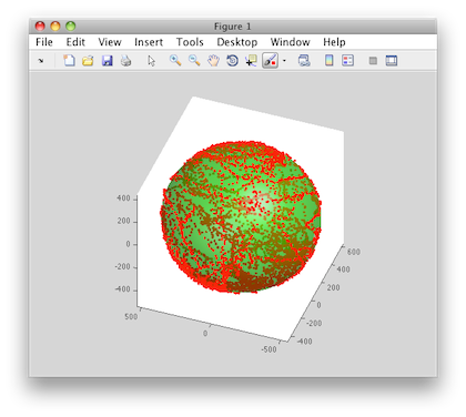
The collected data (the dots) are also written to a file magnetom.float in the sketch folder. Now in case you own Matlab, under Matlab/magnetometer_calibration you’ll find a script called magnetometer_calibration.m that uses this file and produces some plots for you, so you can visually check the calibration.
Ellipsoid fit and corrected values:

-
Sampled raw magnetometer values:

-
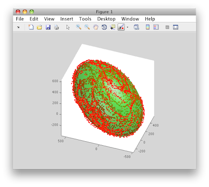
Ellipsoid fit and corrected values:

-
Sampled raw magnetometer values:

-
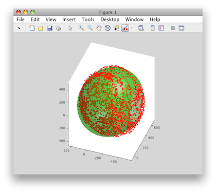
Ellipsoid fit and corrected values:

See Arduino/Razor_AHRS/Razor_AHRS.ino for a list of commands and modes Razor AHRS understands, as well as other useful information. You can also set some firmware parameters there, e.g. the default output modes.
Please see Troubleshooting
One good thing about using the tracker with Bluetooth is, that the board will not be reset when you connect (see About auto-reset).
Another good thing is, that synching (see About synching) will happen automatically if OUTPUT__HAS_RN_BLUETOOTH is set to true in Arduino/Razor_AHRS/Razor_AHRS.ino. The first byte you receive after connecting definitely belongs to a new Razor AHRS output frame. You don’t have to use that, but it makes life easier.
In order for this to work you have to do some one-time-setup on the Bluetooth modem. If you’re using the Bluetooth Mate or a compatible module by Rovering Networks it works like this:
- Upload the file
Arduino/Configure_BT_Dummy/Configure_BT_Dummy.inoto the Razor via USB using the Arduino Software. - Switch the tracker to use Bluetooth instead of USB (see How to put it together) and turn it on using the little
ON/OFFswitch on the board. - Create a virtual serial port for the Bluetooth modem. How you do it depends on your OS, on Mac OSX you do via the Bluetooth Preferences. The default PIN of the modem very likely is
0000or1234. - In Arduino set the Serial Port to the one you just created.
- Switch the Razor
OFFandONagain to restart the Bluetooth modem. - Then within the next 60 seconds (LED on the modem blinks fast) fire up the Serial Monitor. Make sure the setting at the bottom says
"No line ending".- On Mac OSX you could also use ZTerm to do that. Holding the shift key on ZTerm start allows you to select the serial port.
- When connected hit CMD+k to bring up an input field to send text over the serial connection.
- Now (still in the 60 second frame) send
$$$, which brings the modem into command mode. - Change the Serial Monitor from
"No line ending"to"Both NL & CR"(it’s strange, but entering command mode while"Both NL & CR"is set doesn’t work). - You can now configure the modem by sending:
-
SU,57to set the baudrate to57600. -
SO,#to set the prefix forCONNECT/DISCONNECTmessages sent to the Razor to#. - TODO: Latency and power saving options
-
- Send
---to end configuration - Change
"Both NL & CR"back to the default"No line ending". - Close Serial Monitor, switch the tracker back to use USB (as mentioned before, make sure you also disconnect the battery before connecting the board to your computer) and upload the Razor AHRS Firmware from
Arduino/Razor_AHRS/Razor_AHRS.inoagain.
NOTE: These 60 seconds are called Config Timer. Like described above it’s the time frame after power-up in which you can enter command mode. I experienced that the modem always drops the connection if you transmit too much data in this kind of "wait mode". This is also the reason why we uploaded Configure_BT_Dummy.ino: it has no output.
This also means that if you’re actually using the tracker, after switching it on you’d have to wait until Config Timer is over. You can either wait the full 60 seconds before connecting or change the Config Timer to - let’s say 15 seconds - by sending ST,15 while in command mode. Do not make it too short, with 15 seconds you already have to hurry if you want to enter command mode next time. Connecting via Bluetooth just takes more time than just opening a normal serial port connection.
Keep in mind that Bluetooth almost never works full 100% like it should (at least that’s my experience). If you have trouble connecting, switching things off and on again or using another computer with different Bluetooth hardware or a different Bluetooth stack is definitely worth a try.
There is a library and a test app on how to use Razor AHRS with Android in the Android/ subdirectory.

Everything said in the previous section of course also applies when using the Razor with Bluetooth on Android. But Bluetooth seems to be even more picky on Android than it is anyway, so be prepared that it sometimes just won't connect for no apparent reason. Waiting a bit and retrying mostly helps. If not, switch Bluetooth off and on again in the Android system settings and/or reset your Bluetooth modem by power-cycling it. Maybe also wait a bit before trying to connect again, so Bluetooth can do it's magic. How well it actually works really differs from device to device.
On the devices tested it seemed necessary that the Razor is not sending data when not connected (meaning streaming output disabled, Stat LED off). Otherwise connections get reset right away. Most likely this has something to do with internal buffering. Try this:
- If you have a Rovering Networks Bluetooth modem (e.g. the Bluetooth Mate) you can solve this easily by setting
OUTPUT__HAS_RN_BLUETOOTHtotruein the Razor AHRS Firmware. - If you have a different modem, you can still set
OUTPUT__STARTUP_STREAM_ONtofalsein the firmware, but you’d have to reset the Razor manually if an open Bluetooth connection is broken by error, because the Razor would remain in streaming output mode after the connection was broken. Keep an eye on the Stat LED on the Razor: it should be off when Bluetooth is not connected.
Other Android Bluetooth bugs you might see:
- The Android Bluetooth subsystem floods the log with so many messages that it overflows after a few seconds.
- Canceling while connecting sometimes blocks - although it shouldn’t.
- Android does a kind of "half-connect", so that the connection-LED of the modem lights up, but the app hangs on the connect in a non-cancelable way.
- Trying to connect to an already-connected modem hangs in a non-cancelable way
When you use the Razor AHRS in binary output mode and the board does not auto-reset (see next section) on connect, you can not tell where one output frame (yaw/pitch/roll) ends and the next one starts. That is because you tune in to the stream at a random position. Just send a synch request, e.g. #s12 to the Razor and it will reply with the synch token #SYNCH12\r\n. After that starts a new output frame. This mechanism is used in the Processing test sketch and the C++ and Android libraries.
Like most of the Arduino boards, the Razor has an auto-reset feature, which allows the Arduino Software to reset the board via USB using the DTR line. That way you don’t have to press the reset button every time you upload a program to the board. The dark side of this is, that it will also cause a reset every time software on your computer opens a serial connection to the board via USB, thus every time restarting the Razor AHRS Firmware. More details about the auto-reset feature can be found here (see section "Automatic Reset").
Auto-reset does not happen when connecting via Bluetooth.
Auto-reset is bad, if you want to send commands to the Razor right after you connect (most likely because you want to synch and/or set the output mode). Because the on-board bootloader is running for a short time after power-up, your commands will get lost. You have these options:
-
Always use auto-reset via USB and set up the firmware defaults in
Arduino/Razor_AHRS/Razor_AHRS.inoso you don’t have to send any commands at all.- Pro: works with binary and text output.
- Con: relies on hardcoded firmware defaults, relies on auto-reset via USB, does not work with Bluetooth.
-
Always disconnect the DTR pin on the board when using USB, so auto-reset does never happen and you can send commands immediately after connect.
- Pro: works with USB and Bluetooth, no need to rely on firmware defaults.
- Con: you need two cables now: one with DTR to upload the firmware to the board and one without DTR to actually use it.
-
Don’t care if auto-reset happens, but set up firmware defaults in
Arduino/Razor_AHRS/Razor_AHRS.inoso you don’t have to send any commands at all. Have to use text output mode.- Pro: works with USB and Bluetooth, no need for a second no-DTR cable.
- Con: relies on hardcoded firmware defaults, does not work with (faster) binary output mode.
-
Don’t care about anything :)
In that case you can send commands to set the desired output mode. In case you’re using binary output mode you’d also have to synch. Because there might be a reset, you need to wait until AHRS is up and running and send your commands then, so they won’t get lost. But how to know when it’s up and running?
The easy way is to wait a long-enough time (3 seconds should be ok) after opening the serial port until you send your commands to the Razor (for the sake of simplicity, that is what I did in the Processing test sketch).
The more complicated but much faster way is to send synch requests to the Razor in 200ms intervals until it answers. We then know we’re heard and can send our actual commands (to make it work with every setup, that’s what I did in the C++ and Android libraries).
- Pro: universal: works with USB and Bluetooth, works with binary and text output mode, no need to rely on any firmware defaults.
- Con: harder to code than the other options.
You see, it’s really a question of which setup(s) you want to support. Even if a little harder to code, 4. might be the best option because it always works.
Internally the fusion of accelerometer, magnetometer and gyroscope data is done using a Direction Cosine Matrix (DCM) algorithm. The algorithm also takes care of handling sensor noise and numerical errors. It is based on this paper by William Premerlani. For even more detailed information have a look at these papers by Robert Mahony.
Based on the calibration measurements you compile into the firmware (see Sensor calibration), the firmware tries to compensate all three sensors for:
- wrongly scaled sensor axes: e.g. if the accelerometer x-axis measures 200 units, whereas the accelerometer y-axis measures 230 units with the same force applied. All three axes per sensor should be consistent.
- zero offsets: e.g. if any of the gyroscope axes reports something different than zero when the board is not moving.
Right now these compensations are not adaptive over time. They stay the same and they’re only as good as the calibration measurements you hardcode into the firmware.
The magnetometer has some particularities when it comes to calibration, since there are not only internal sensor inaccuracy and noise, but also external magnetic field distortions. Good magnetometer performance is most crucial to yield a correct heading in all directions - so if you calibrate in a distorted environment, you will always have errors.
There are several types of magnetic field distortions. First of all there is soft iron and hard iron distortion. Second, the source(s) of distortion can be relative to the sensor (i.e. moving and rotating
with the sensor) or independent from the sensor (bound to the world or moving independently in the world).
To learn about soft iron and hard iron distortion and possible compensation approaches, have a look
here, here and here.
Currently the calibration compensates for hard and soft iron errors, where the iron moves/rotates with the sensor. Compensating for hard/soft iron errors where the source of distortion is not bound to the sensor is only possible to a certain degree and requires quite complex adaptive algorithms. There are no plans on adding compensation for these kinds of errors in the near future.
The most common problem when using the tracker (like with all these kinds of trackers that are "self-contained" and don't have a fixed "base-station") is drift in the horizontal plane. Originally drift means that the yaw angle is constantly drifting away in one direction. This is caused by the gyroscope which is never actually outputting zeros, even when the board is lying still. This is called sensor noise and mis-calibration and even though you (hopefully followed the tutorial and) calibrated the gyro, it will always be a little off. It's a cheap gyro after all. Now what you most likely experience as drift or false yaw readings is actually caused by a flawed drift-correction in the firmware itself. The firmware constantly uses the magnetometer and accelerometer data to calculate a magnetic north. This magnetic north is then used to correct gyroscope drift. So if you do a fast rotation and then see the yaw slowly drifting back (or forth) and "locking in" on a certain angle, then this is caused by a flawed drift-correction due to false magnetometer data. If your drift is constant without "locking in" then this is gyroscope-drift, which is very unlikely to happen if you calibrated the sensors. Here's a little summary of things that you can do and check to improve magnetometer-related drift:
- Check that you really selected the right hardware in
Razor_AHRS.ino(see Setting up the software)! - Try setting
DEBUG__NO_DRIFT_CORRECTIONinRazor_AHRS.inoto true temporarily. The magnetometer will not be used. Yaw should be more stable, but you'll have the constant gyroscope drift mentioned earlier, which makes it unusable in the long run. But at least you know it's a magnetometer issue now. - Calibrate the sensors, and especially the magnetometer (see Sensor calibration). Use the Extended magnetometer calibration in the exact setup and environment that you plan on using the Razor in. Any objects that actively or passively influence the magnetic field should be present during calibration and keep their position relative to the Razor after calibrating. They can move with the Razor - as long as they keep their relative position everything is fine and even strong distortion can be "calibrated away". Magnetic fields that change over time on the other hand - like the ones generated by nearby motors that are turned on and off - can not be handled with the current static calibration.
- If all this didn't help, it's also possible that one or some of your sensors are broken. You should see this when calibrating them: they are either stuck on one value or the values they output are very far off the ones given in the default calibration in
Razor_AHRS.ino.
The most common problem is that the serial port is not set correctly. To fix this find the messages/console output at the bottom of the Processing window. Scroll to the top and find the list of serial ports available. Note the number of the serial port you want to use, then find the line in the sketch code where it is saying final static int SERIAL_PORT_NUM = 0;. Replace 0 with your number.
Have a look at the Issues Page.
If the code and the tutorial helped you and you'd like to buy me a beer to say thanks, I'll be happy and say cheers!
PayPal:

 This Tutorial is licensed under a Creative Commons Attribution-NonCommercial-ShareAlike 3.0 Unported License. The code is licensed under GPLv3.